


PRO
3
Side Mount Packaged Refrigeration System Installation and Operations Manual, May 2008 7
PRO
3
Side Mount Packaged Refrigeration System
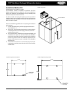
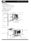
Electrical Connection
1. Refer to all local codes for proper connection.
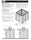
2. A knock-out is provided for 1" conduit on the side of the
condensing unit section above the electrical box. See FIGURE 12.
3. Wire will be brought into the electrical box through the
bottom of the electrical box and connected to the top of the
contactor.
Refrigeration Sequence of Operation
1. Power is provided to the temperature control, compressor
contactor and cooler evaporator fans.
2. The temperature controller closes and energizes the
compressor contactor, starting the compressor, evaporator
and condenser fan(s).
3. When the system reaches the desired box temperature, the
temperature control will de-energize the compressor contactor.
Evaporator fans will continue to operate at this point.
4. When the xture temperature rises above the set point
and minimum o-time has elapsed, the temperature control
will close and re-energize the compressor contactor.
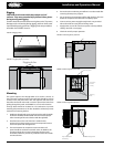
Coolers: Air-defrost Operation
Air defrost units are pre-programmed for 4 defrost per day. These
periods are reprogrammable. When the coil temperature reaches
38°F, the control will terminate the defrost cycle.
For programming information see pages 7-16.
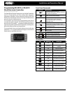
Cooler with Electric Defrost and Freezer
Temperature/Defrost Control
PRO
3
packaged refrigeration system cooler with electric defrost and
freezer units come factory equipped with an electronic temperature/
defrost control.
For programming information see pages 7-16.
Cooler with Electric Defrost and Freezer
Sequence of Operation
Power is provided to the temperature control and compressor
contactor. The drain line heater as well as the crankcase heaters will
also have continuous power supplied to them.
The temperature controller energizes the compressor contactor,
starting the compressor and condenser fan(s). The evaporator fans
will be energized by the electronic controller.
When the system reaches the desired box temperature, the
temperature control will de-energize the compressor contactor and
the evaporator fans.
When the temperature rises above the set point and minimum o-
time (4 minutes) has elapsed, the temperature control will close and
re-energize the compressor contactor.
1. During normal operation, at the preset times of day, the
temperature/defrost control will de-energize the compressor
contactor and evaporator fans and energize the defrost
heaters. These functions are controlled through relays on the
controller.
2. When the coil has defrosted fully and has reached the preset
coil temperature (as sensed by the coil temperature sensor)
the defrost heater de-energizes and the fan delay and drip
sequences begin.
3. The temperature/defrost control energizes the compressor
contactor, starting the compressor and condenser fan(s).
4. Freezer evaporator fans will be energized by the temperature/
defrost control when the coil temperature reaches 35°F or fan
delay time has elapsed.
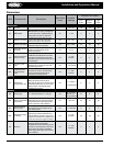
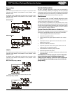
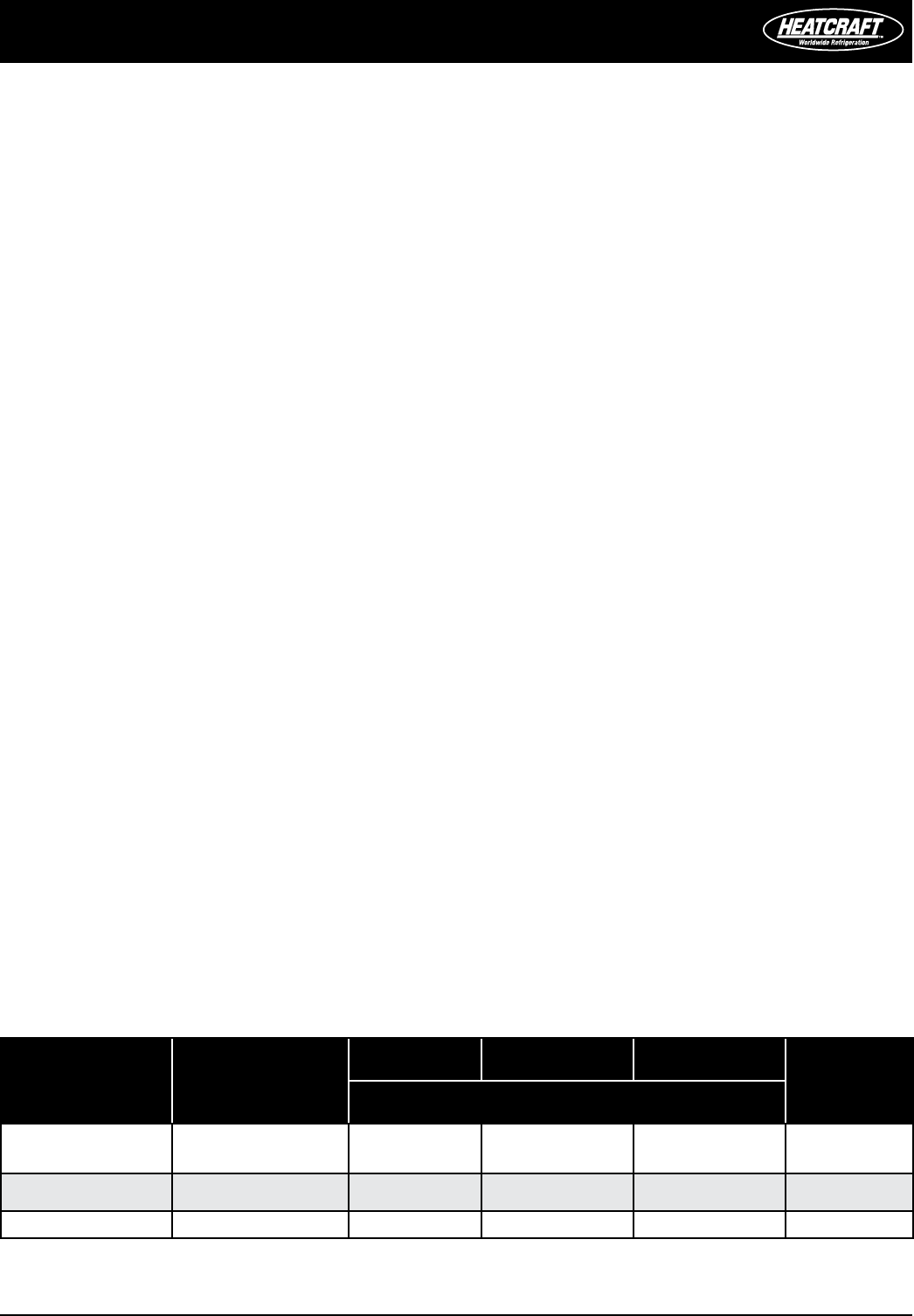
Application:
Temperature set
points
Defrost start times
Defrost
Duration
Drip Time Fan Delay
Defrost
Termination
Set Point
Minutes
Cooler: 35˚ F
Every 3 hours of
compressor run time
60 – – 38˚ F
Cooler w/ Electric
Defrost: 34˚ F
40 2 2 65˚ F
Freezer: -10˚ F 4 times / day 40 2 2 65˚ F
TABLE 1 Model PST | Default Temperature Control Settings