--- 16 ---
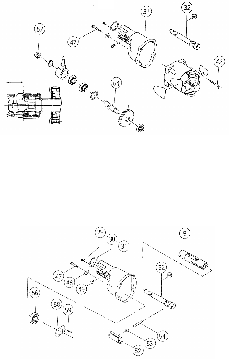
Loosen the Nylock Bolt (W/Flange) M6 x 35 [47] which secures the fan of the armature ass'y (approximately
two turns). Remove the four Machine Screws (W/Washers) M5 x 60 [42] and then pull out the Gear Cover
[31] from the main body. Remove the Nylock Bolt (W/Flange) M6 x 35 [47], then Second Shaft (A) [64]
section and the Sub Shaft [57] can be removed from the Gear Cover [31]. At this time, Second Shaft (A) [64]
section can be easily removed after first pulling out the tip of the Plunger (A) Set [32] approximately 20 mm
from the Gear Cover [31].
Fig. 3
Remove the two FT-Machine Screws M4 x 6 [29] and remove the Felt Cover [30]. Secure the Gear Cover
[31] and remove the two Bolts M10 [49] to remove the two Swing Rails [52] from the inside of the Gear Cover
[31]. Pull out the Guide Sleeve Ass'y [9] from the gear cover, then Plunger (A) Set [32] and the Guide Sleeve
Ass'y [9] can be removed in an assembled state. At this time, remove the Swing Roller [53] with the Pin D6
[54] mounted. Remove the two Machine Screws M4 x 10 [59] from the inside of the gear cover and then
remove Bearing Cover (B) [58] and the Ball Bearing 6003DDCMPS2S [56].
Fig. 4
20


