


--- 19 ---
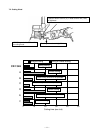
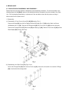
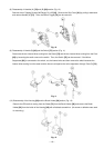
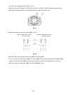
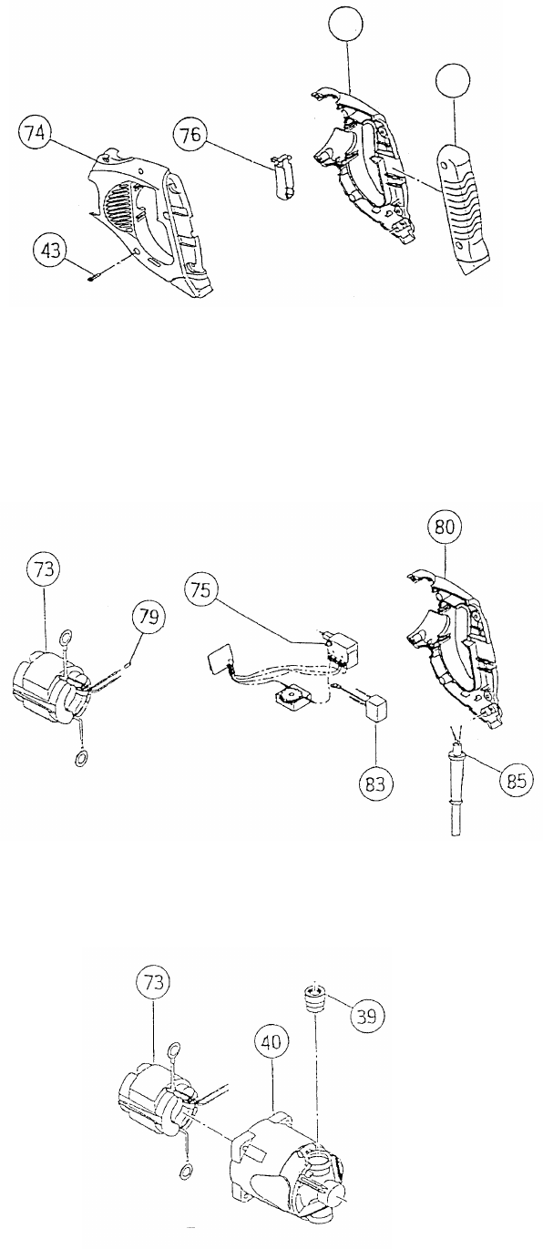
(8) Disassembly of Handles (A) [74] and (B) [80] section (Fig. 10)
Remove the six Tapping Screws (W/Flange) D4 x 25 [43]. Remove the Grip Cover [81] by pulling it backward
and remove Handle (A) [74]. Then, the Switch Trigger [76] can be removed.
Fig. 10
Fig. 11
Fig. 12
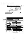
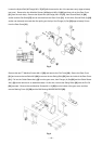
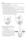
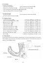
(9) Disassembly of Handle (B) [80] and the Switch [75] section (Fig. 11)
Disconnect the two internal wires coming from the Stator [73] and the two internal wires coming from the Cord
[85] by loosening the small screw on the switch. Then, the Switch [75] can be removed. If the Noise
Suppressor [83] is connected to the switch, cut the internal wires and then remove the switch because the
internal wires coming from the stator and the triac are crimped to the noise suppressor through Tube (D) [79].
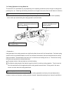
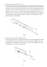
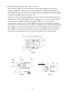
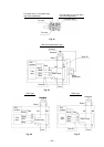
(10) Disassembly of the Housing [40] and the Brush Holder [39] section (Fig. 12)
Remove the CB terminal coming from the Stator [73] from the Brush Holder [39] and remove the Brush
Holder [39] from the inside of the Housing [40] with a flatblade screwdriver. (No screw or adhesive was used
for mounting.)
80
81