


--- 21 ---
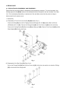
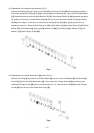
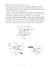
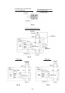
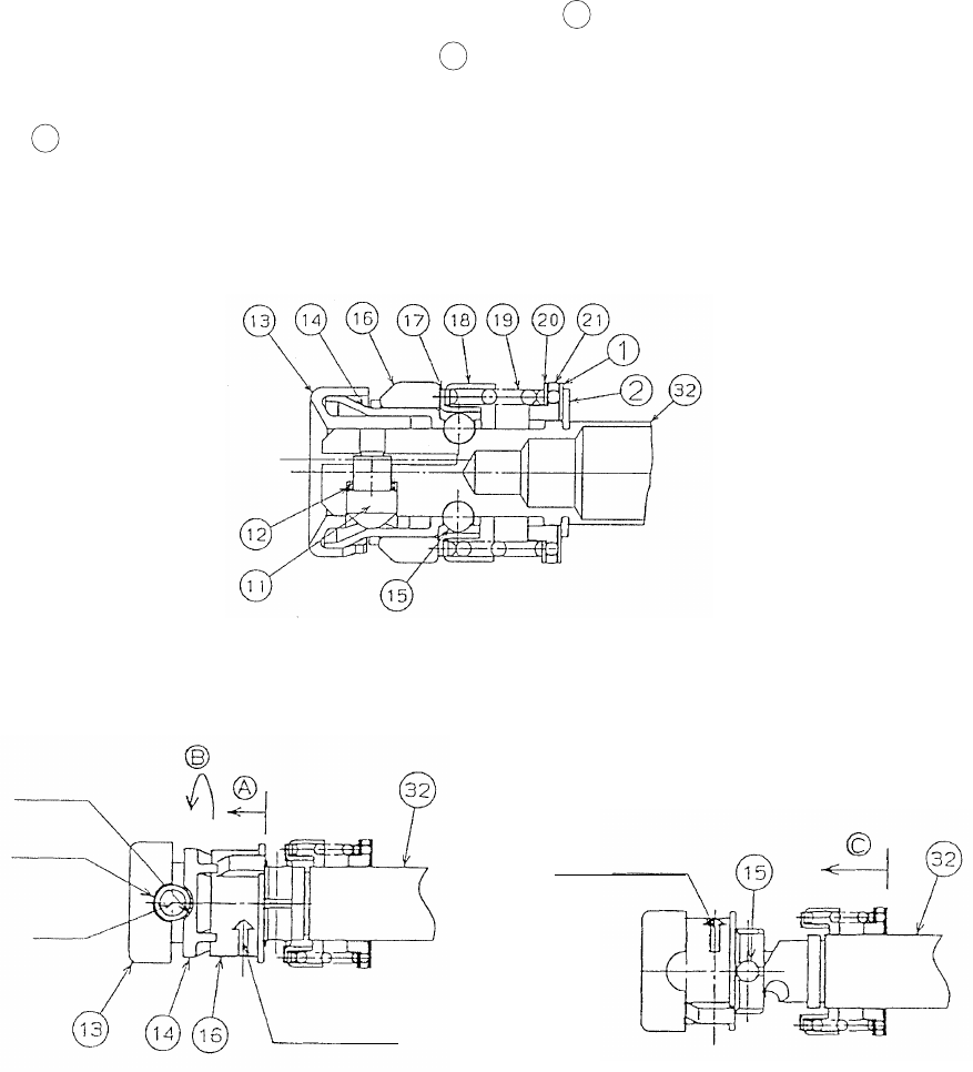
(3) Reassembly of the blade mounting section (Figs. 15, 16 and 17)
Apply Doubrex 251 grease to the inner circumference of Holder Sleeve (B) [14] and the cam groove of
Plunger (A) Set [32]. Mount Washer (E) [1], Thrust Bearing [21], Washer (D) [20], Spring (A) [19], Dust
Washer [18], Guide Washer [17], Holder Sleeve (C) [16], Holder Sleeve (B) [14] and Holder Sleeve (A) [13] in
the Plunger (A) Set [32] through the tip in order (Fig. 15).
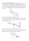
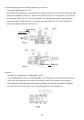
Next, align the hole of the Plunger (A) Set [32] with the notches of Holder Sleeve (A) [13] and Holder Sleeve
(B) [14] and then insert Spring (B) [12] and the Holder Pin [11] into the hole. Push in the Holder Pin [11] to
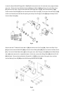
eject Holder Sleeves (B) [14] and (C) [16] forward (as shown in Fig. 16). Turn them about 90˚
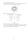
counterclockwise viewing from the tip (as shown in Fig. 16), then insert the two Steel Balls D4.76 [15] (in
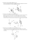
the direction of the arrow marks shown in Figs. 16 and 17). Slide all the parts up to Washer (E) [1] forward (as
shown in Fig. 17) and mount the Retaining Ring (E-type) for D14 Shaft [2] securely by adjusting Spring (A)
[19]. Be careful of the projections and depressions on Holder Sleeve (B) [14] and Holder Sleeve (C) [16]
when mounting. After reassembly, test mount and remove a saw blade to check for proper operation.
Fig. 16
Fig. 15
Fig. 17
C
Hole
Notch
Notch
Arrow mark
Arrow mark
A
B