


– 8 –
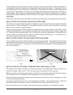
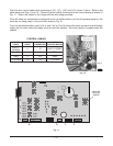
INTERNAL ELECTRICAL CONNECTIONS
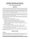
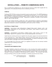
Remove the lid from the electrical box on top of the cabinet (Fig. 8). On the front of the cabinet, remove
two screws and swing the control panel open. On the front of the cabinet beside the control panel, turn
the black knob and swing the printer panel open.
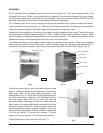
From the top of the cabinet, inside the electrical box, insert a short plastic tube into the plastic tubes
foamed into the door frame panel. Refer to
TUBE #1 and TUBE #2 in Fig. 8.
Fig. 8
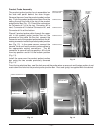
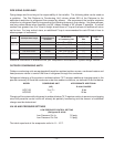
Push the power wires connector, labeled M, down through TUBE #1 (Fig. 8) to the recess behind the
control panel. Connect this connector (which includes 6 wires for the door switch, door frame heaters
and on-off switch) to its mating connector, labeled M (Fig. 9).
Feed the terminal for the two small black and two small red wires from the printer(s) up through the
empty TUBE #2 (Fig. 8) and connect it to terminal [ CN2 ] on the printer power supply board (Fig. 8).
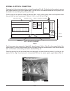
Fig. 9
PL-41540-1
JOIN POWER WIRE CONNECTORS
F
R
O
N
T
LEFT SIDE OF CABINET
C
A
P
A
C
I
T
O
R
S
C
A
P
A
C
I
T
O
R
S
PRINTER
POWER
SUPPLY
BOARD
CONTROL
POWER
SUPPLY
BOARD
I / O
BOARD
TERMINAL [ CN2 ]
CABLE TO PRODUCT PROBES
ELECTRICAL BOX
TUBE #1
TUBE #2
TUBE #3
TUBE #4