


– 4 –
INSTALLATION
Immediately after unpacking the oven, check for possible shipping damage. If the
oven is found to be damaged, save the packaging material and contact the carrier
within 15 days of delivery.
Prior to installation, test the electrical service to make sure that it agrees with the
specications on the machine data plate located at the lower outside corner of the
oven.
LOCATION
The oven must be installed on a level surface within 5 feet of both an open drain
and a hot water supply. The installation location must allow adequate clearances
for servicing and for proper operation. Suitable space is needed for the grease
container and the chemical cleaner supply bottle and for access at the doors. For
stacked and countertop congurations, the minimum clearance on the right side
for plumbing and electrical connections is 3". For out-of-sight, drop-through utility
connection into the stand accessory, 0" clearance is required on all sides. Wood
laminates, veneers, etc. are unsuitable materials for use in areas exposed to self-
cleaning oven, steam and detergents. The rotary oven must not be installed in
high-moisture environments such as meat rooms or where high pressure cleaning
is used.
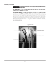
LEGS, CASTERS OR STAND ACCESSORIES
A set of four 4" tall legs is available as an accessory. Casters are included with the
stacking kit accessory. An oven stand accessory is available; the oven is mounted
on top of the stand.
Tethering is required for units equipped with casters, either on a stand or stacked.
Refer to the Stand or Stacking Kit Instructions for additional installation
information.
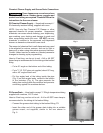
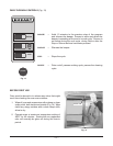
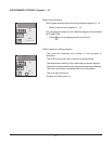
CONNECTION INFORMATION — GENERAL
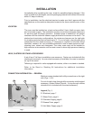
Machine comes standard with utility connections on the right
side (Figs. 1 & 2).
For out-of-sight, drop-through utility connection into the stand
accessory, contact Hobart Service. A drop-through utilities
relocation kit is included with the stand accessory.
Legend (Fig. 1)
E1 Electrical, page 7.
P1 Water Drain, page 5.
P2 Chemical Supply, page 6.
P3 Grease Drain, page 6.
P4 Hot Water Supply, page 5.
Fig. 1
E1
P1
P4
P3
P2