– 11 –
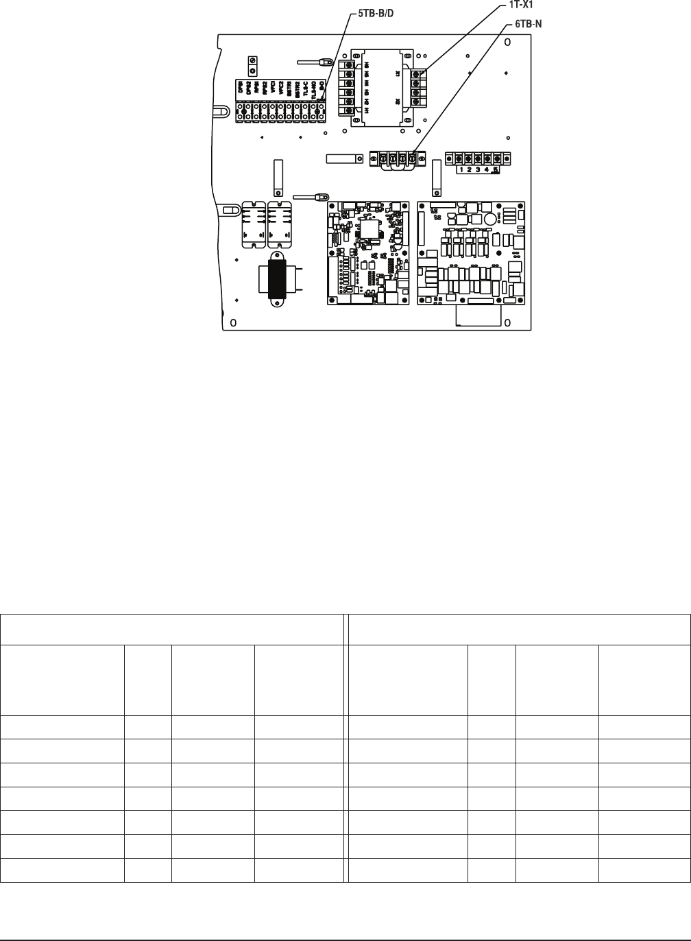
Power Connections
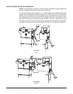
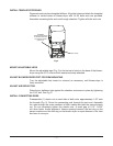
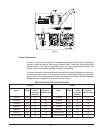
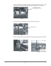
Remove two screws securing the component baseplate and slide the baseplate
forwardtogainaccesstoeldwiringterminalblock.Routetheeldwiringleads
through hole in the side of the blower-dryer unit using appropriate conduit and
ttings.Allowextralengthinleadsforproperconnections.
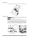
Connect the leads to the terminal block located at the back of the blower-dryer unit.
Connect the ground wire to the ground terminal located beside the main terminal
block. Refer to the table below for proper connection information. Slide component
baseplate back in position and secure with two bolts.
BRANCH CIRCUIT SIZE AND PROTECTION
Electric Steam
Electrical
Specs.
Rated
Amps
Min. Supply
Circuit
Conductor
Ampacity
Max.
Protective
Device Amps
Electrical
Specs.
Rated
Amps
Min. Supply
Circuit
Conductor
Ampacity
Max.
Protective
Device Amps
208/60/3 34.2 45 45 208/60/3 4.5 15 15
240/60/3 30.7 40 40 240/60/3 4.5 15 15
380/60/3 17.8 25 25 380/60/3 2.6 15 15
480/60/3 15.7 20 20 480/60/3 2.6 15 15
600/60/3 12.6 20 20 600/60/3 2.1 15 15
200/50/3 33.0 45 45 200-240/50/3 4.5 15 15
380-415/50/3 17.8 25 25 380-415/50/3 2.6 15 15
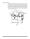
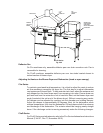
Fig. 11


