


8300614000
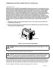
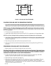
CONNECTING ELECTRICAL POWER CIRCUIT TO REMOTE CONDENSER COIL AND
FAN ASS’Y
(see Figure 5 and 9)
CAUTION: The Cooling Unit refrigeration system is cooled by a Remote Condenser Coil
and Fan Assembly (P/N 309602000) that is authorized by IMI Cornelius Inc. Use of an
unauthorized Remote Condenser Coil and Fan Assembly will automatically void the
Cooling Unit factory warranty.
NOTE: Electrical power circuit may be connected to the Remote Condenser Coil and Fan Assembly
(P/N 309602000) in two ways. The preferred way is to draw electrical power from the cooling unit
contactor which allows the Remote Condenser Coil and Fan Assembly to operate only when the
cooling unit refrigeration system is operating. The optional way is to connect a separate electrical
power circuit (independent of the cooling unit) through an appropriately rated and fused disconnect
switch or an equivalent HACR circuit breaker which allows the Remote Condenser Coil and Fan
Assembly to operate at all times (independent of cooling unit operation).
1. Connect and route electrical power circuit cable from Remote Condenser Coil and Fan Assembly through
fuse box (not provided), fused at 15-amps (maximum) down to Cooling Unit location. REMOTE
CONDENSER COIL AND FAN ASSEMBLY MUST BE PROPERLY GROUNDED, POWER CIRCUIT
MUST BE MADE UP OF COPPER CONDUCTORS, AND ALL WIRING MUST CONFORM TO NATIONAL
AND LOCAL ELECTRICAL CODES.
2. Route Remote Condenser Coil and Fan Assembly Power cable electrical wires through electrical handy
box on back of Cooling Unit to inside of electrical control box.
3. Connect Remote Condenser Coil and Fan Assembly power cable electrical wires to T
1
and T
2
terminals on
contactor inside Cooling Unit electrical control box.
4. Install electrical control box cover and secure with four screws.
5. Install cover on electrical handy box on back of Cooling Unit.
CONNECTING PLAIN WATER INLET SUPPLY LINE TO COOLING UNIT
(see Figure 2)
NOTE: IMI Cornelius Inc. recommends that a water shutoff valve be installed in plain water inlet supply
line connected to Cooling Unit and that water supply be filtered. WATER PIPE CONNECTIONS AND
FIXTURES DIRECTLY CONNECTED TO A POTABLE WATER SUPPLY SHALL BE SIZED, INSTALLED
AND MAINTAINED ACCORDING TO FEDERAL, STATE, AND LOCAL LAWS.
CAUTION: Plain water inlet supply line to Cooling Unit must be 1/2-inch I.D. minimum.
Check water flow rate of water inlet supply line. MINIMUM FLOW RATE MUST BE AT LEAST
300-GALLONS PER HOUR. If flow rate is less than 300-gallons per hour, ‘ ‘starving’’ of
carbonator water pump will occur. Starving will allow water pump to overheat causing safety
thermostat on pump outlet to disrupt electrical power to and stop water pump motor. Carbonated
water circulating pump overheating could occur if water inlet supply line flow rate drops below
300-gallons per hour. INCOMING PLAIN WATER INLET SUPPLY LINE WATER PRESSURE MUST
REMAIN A MINIMUM OF 10-PSI BELOW THE CARBONATOR CO
2
OPERATING PRESSURE.
(Example: Operating pressure is 90-psi and maximum water pressure can be no more than 80-psi,
etc.)
1. Before connecting plain water inlet supply line to Cooling Unit, open water line shutoff valve for a period of
time to flush out any metal shavings and other contaminates that may have resulted from plumbing
connections.