


13 300614000
OPERATORS INSTRUCTIONS
This section covers operating controls, daily pre-operation check, adjustments, replenishing CO
2
and syrup
supplies, cleaning and sanitizing, Cooling Unit maintenance, Remote Condenser Coil and Fan Assembly
maintenance, lubrication, and servicing CO
2
gas check valves.
WARNING: Disconnect electrical power to Cooling Unit and Remote Condenser Coil and
Fan Assembly to prevent personal injury before attempting any internal maintenance. Only
qualified personnel should service internal components or electrical wiring.
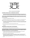
OPERATING CONTROLS
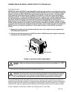
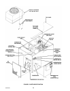
COOLING UNIT REFRIGERATION POWER SWITCH
(see Figure 5)
REFRIGERATION POWER switch, located on front of Cooling Unit, placed in ‘‘OFF’’ position will interrupt
electrical power to refrigeration compressor, agitator motor, compressor cooling fan, carbonated water
circulating pump, and the carbonator pump motor. REFRIGERATION POWER switch placed in ‘‘ON’’ position
will start the carbonator pump motor (if carbonated water is being called for), the carbonated water circulating
pump motor, and the agitator motor. Under certain conditions approximately 2-1/2 minutes after the
REFRIGERATION POWER SWITCH has been placed in ‘‘ON’’ position refrigeration compressor and
compressor cooling fan will start.
COOLING UNIT CARBONATOR MOTOR SWITCH
(see Figure 5)
CARBONATOR MOTOR power switch, located on front of Cooling Unit, placed in ‘‘OFF’’ position will interrupt
electrical power to carbonator pump motor. Switch must be placed in ‘‘ON’’ position before carbonator pump
motor will operate.
COOLING UNIT CIRCULATING MOTOR SWITCH
(see Figure 5)
CIRCULATING MOTOR power switch, located on front of Cooling Unit, placed in ‘‘OFF’’ position will interrupt
electrical power to carbonated water circulating pump. Switch must be placed in ‘‘ON’’ position before circulating
pump will operate.
REFRIGERATION SYSTEM TEMPERATURE SENSING DEVICE AND HIGH-PRESSURE
CUTOUT SWITCH
(see Figure 5)
This Cooling Unit is equipped with a refrigeration system temperature sensing device and a high-pressure
sensing cutout switch that will shut refrigeration system down should the system overheat due to a clogged
condenser coil in the Remote Condenser Coil and Fan Assembly. If refrigeration system does not automatically
restart itself after system has cooled down, high-pressure sensing cutout switch (see Figure 5) will have to be
pressed to reset switch. MAKE SURE REFRIGERATION SYSTEM PROBLEM IS CORRECTED. OPERATING
REFRIGERATION SYSTEM IN THIS MANNER FOR PROLONGED PERIOD OF TIME COULD RESULT IN
COMPRESSOR FAILURE.