


11 300614000
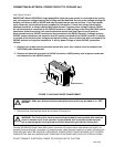
5. Adjust carbonator secondary CO
2
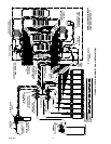
regulator (see Figure 2) to a nominal 90-psi. Loosen CO
2
regulator
adjusting screw locknut. Turn adjusting screw to the right (clockwise) until regulator gage registers nominal
90-psi, then tighten adjusting screw lock nut. CO
2
PRESSURE TO CARBONATORS MUST NOT EXCEED
120-PSIG.
OPERATION
WARNING: Disconnect electrical power to Cooling Unit and Remote Condenser Coil and
Fan Assembly to prevent personal injury before attempting any Cooling Unit or Remote
Condenser Coil and Fan Assembly internal maintenance. Only qualified personnel should
service internal components or electrical wiring.
CAUTION: to prevent Hydro-Boostâ coil freeze up during initial Cooling Unit start-up, the
following start-up procedure must be performed as follows:
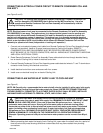
1. Make sure Hydro Boostâ bypass shutoff valve inside Cooling Unit (see Figure 2) is in ‘‘CLOSED’’ (handle
not in line with tubing) position.
2. Make sure Cooling Unit REFRIGERATION POWER, CARBONATOR MOTOR, and CIRCULATING
MOTOR Power switches are in ‘‘OFF’’ positions.
3. Connect electrical power to Cooling Unit at disconnect switch. Connect electrical power to Remote
Condenser Coil and Fan Assembly at disconnect switch.
4. Place CARBONATOR MOTOR power switch in ‘‘ON’’ position.
5. Place REFRIGERATION power switch in ‘‘ON’’ position. Agitator motor and carbonator pump motor only
will start and fill Hydro-BoostR coil with plain water. APPROXIMATELY 2-1/2 MINUTES AFTER
CARBONATOR PUMP MOTOR HAS STARTED, REFRIGERATION COMPRESSOR, AND
COMPRESSOR COOLING FAN, WILL START.
NOTE: As ice bank forms in water tank, water expansion will take place and excess water will escape
through water tank overflow hose to permanent floor drain.
Cooling Unit will begin forming an ice bank and refrigerated Hydro-Boostâ coil will also be chilling water. When
full ice bank has been formed, Cooling Unit compressor and compressor cooling fan will stop but agitator motor
will continue to operate circulating ice water bath in water tank.
6. Dispense from dispensing station until carbonated water appears at dispensing valve which indicates
Cooling Unit plain and carbonated water systems have been filled.
7. Place CIRCULATING MOTOR power switch in ‘‘ON’’ position. Circulating pump will start and begin
circulating carbonated water in carbonated water circulating system as explained in SYSTEM THEORY OF
OPERATION in GENERAL INFORMATION SECTION.
8. Dispense carbonated water from dispensing valve to make sure all air has been purged from system.
9. If Cooling Unit plain water outlet line has been connected to a dispensing station dispensing valve,
dispense from valve until all air has been purged from plain water system.
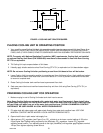
10. Adjust soft drink tanks secondary CO
2
regulators (see Figure 2) as follows:Sugar
Syrup Soft Drink Tanks CO
2
Regulator.
Adjust sugar syrup soft drink tanks secondary CO
2
regulator at 40-psig for syrup lines up to 10-feet in
length plus one pound for each additional length of 10-feet, plus one pound for each 2-feet of vertical lift.
For example: if syrup line total length is 30-feet and total vertical lift is 6-feet, then 40-psig + 2-psig
(1-pound for every 10-feet of length over 10-feet which is 20-feet) + 3-psig (1-pound for every 2-feet of
vertical lift which is 6-feet); total equals 40 + 2 + 3 = 45-psig CO
2
regulator setting.