


10300614000
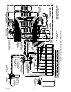
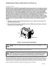
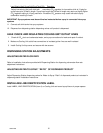
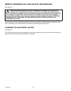
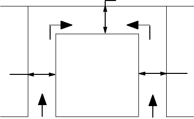
18--IN.
18--IN.
18--IN.
COOLING UNIT
AIR FLOW
(OPEN TO ROOM)
FIGURE 4. COOLING UNIT SPACE REQUIRED
PLACING COOLING UNIT IN OPERATING POSITION
1. Very carefully, move Cooling Unit back into operating position leaving space around Unit (see Figure 4) as
specified in SELECTING LOCATION. MAKE SURE THERE ARE NO KINKS IN COOLING UNIT INLET
LINES, AND (IF APPLICABLE) REMOTE CONDENSER AND FAN ASSEMBLY REFRIGERATION LINES.
NOTE: To comply with National Sanitation Foundation (NSF) requirements, Cooling Unit not installed
on optional Cooling Unit Stand (P/N 309309-069) must have its base sealed to floor with Dow-Corning
RTV 731 or equivalent.
2. Tilt Cooling Unit up to expose bottom of Unit base.
3. Liberally apply silastic sealant such as Dow-Corning (RTV 731) or equivalent on Unit base bottom edges.
NOTE: Do not move Cooling Unit after positioning or seal from Unit base to floor will be broken.
4. Lower Cooling Unit into operating position to complete seal from Unit base to floor. Apply additional sealant
around bottom of base. Seal must have a minimum radius of 1/2-inch to prevent cracks and crevices and
to ensure a complete seal.
5. Route Cooling Unit water tank overflow hose to permanent floor drain.
6. Seal area around drain and overflow hoses where they exit from Unit using Dow Corning (RTV 731) or
equivalent).
PREPARING COOLING UNIT FOR OPERATION
1. Make sure plug in end of Cooling Unit water tank drain hose is secure.
Note: Some Cooling Units are equipped with a water tank water level float control. Open shutoff valve
in plain water inlet supply line. Due to slow water fill rate of the water level float control, water tank may
be hand filled until water runs out of the water tank overflow hose. CLEAN LOW-MINERAL-CONTENT
WATER MUST BE USED WHERE A LOCAL WATER PROBLEM EXIST.
2. Fill water tank with clean water until water starts flowing from water tank overflow hose. USE LOW
MINERAL CONTENT WATER WHERE A LOCAL WATER PROBLEM EXISTS.
3. Open shutoff valve in plain water inlet supply line.
4. Adjust primary CO
2
regulator (see Figure 2) on CO
2
cylinder to a minimum nominal setting of 120-psi or
24-psi higher than highest setting required by the secondary CO
2
regulators. Loosen CO
2
regulator
adjusting screw locknut. Turn adjusting screw to the right (clockwise) until regulator gage registers nominal
120-psi, then tighten adjusting screw locknut.