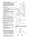
Installing Side Shelf, Side Burner and Tool
Holder Kit
Remove Side Burner from Side Burner Kit before
installing.
1.
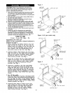
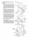
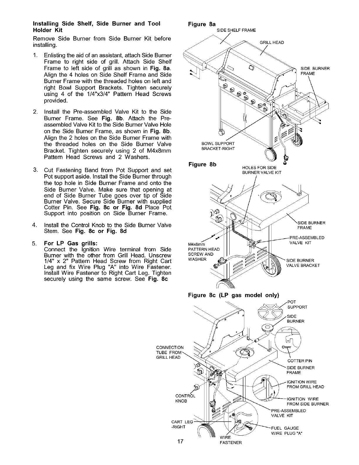
Enlisting the aid of an assistant, attach Side Burner
Frame to right side of grill. Attach Side Shelf
Frame to left side of grill as shown in Fig. 8a.
Align the 4 holes on Side Shelf Frame and Side
Burner Frame with the threaded holes on left and
right Bowl Support Brackets. Tighten securely
using 4 of the 1/4"x3/4" Pattern Head Screws
provided.
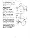
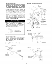
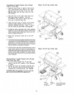
2. Install the Pre-assembled Valve Kit to the Side
Burner Frame. See Fig. 8b. Attach the Pre-
assembled Valve Kit to the Side Burner Valve Hole
on the Side Burner Frame, as shown in Fig. 8b.
Align the 2 holes on the Side Burner Frame with
the threaded holes on the Side Burner Valve
Bracket. Tighten securely using 2 of M4x8mm
Pattern Head Screws and 2 Washers.
.
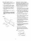
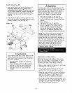
4.
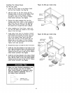
Cut Fastening Band from Pot Support and set
Pot support aside. Install the Side Burner through
the top hole in Side Burner Frame and onto the
Side Burner Valve. Make sure that opening at
end of Side Burner Tube goes over tip of Side
Burner Valve. Secure Side Burner with supplied
Cotter Pin. See Fig. 8c or Fig. 8d Place Pot
Support into position on Side Burner Frame.
Install the Control Knob to the Side Burner Valve
Stem. See Fig. 8c or Fig. 8d
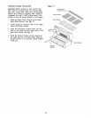
5.
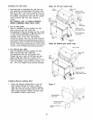
For LP Gas grills:
Connect the Ignition Wire terminal from Side
Burner with the other from Grill Head. Unscrew
1/4" x 2" Pattern Head Screw from Right Cart
Leg and fix Wire Plug "A" into Wire Fastener.
Install Wire Fastener to Right Cart Leg. Tighten
securely using the same screw. See Fig. 8c
Figure 8a
SIDE SHELF FRAME
GRILL HEAD
BOWL SUPPORT
BRACKET-RIGHT
Figure 8b
HOLESFORSIDE
BURNERVALVEKIT
M4x8mm
PATTERN HEAD
SCREW AND
WASHER
SIDE BURNER
FRAME
SIDE BURNER
FRAME
EMBLED
VALVE KIT
RNER
VALVE BRACKET
Figure 8c (LP gas model only)
SUPPORT
,SIDE
BURNER
CONNECTION
TUBE
GRILL HEAD
COTTER PiN
BURNER
FRAME
CONTROL
KNOB
CART
-RIGHT
17
WiRE
FASTENER
FROM GRILL HEAD
WIRE
FROM SiDE BURNER
VALVE KIT
GAUGE
WiRE PLUG "A"


