


Cleaning The Burner Tubes and Burner Ports
To reduce the chance of FLASHBACK the proce-
dure below should be followed at least once a month
in late summer or early fall when spiders are most
active or when your gdll has not been used for a
period of time.
1. Turn all Burner Valves to the full OFF position.
2. Turn the LP gas tank valve to the full OFF position.
3. Detach the LP gas regulator assembly from your
gas grill.
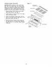
4. Remove the Cooking Grids, Flame tamers, and
Grease Trays from your gdll.
5. Remove the Cotter Pin from the rear underside of
each Burner using a pair of long nose pliers.
6. Carefully lift each Burner up and away from the
Gas Valve Orifice.
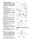
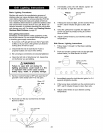
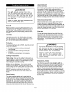
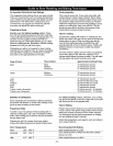
7. Refer to Fig. 1 and perform one of these
three cleaning methods:
Bend a stiff wire, (a lightweight coat
hanger works well) into a small hook as
shown below. Run the hook through the
Burner Tube and inside the Burner several
times to remove any debris.
,)
Use a bottle brush with a flexible handle.
Run the brush through the Burner Tube
and inside the Burner several times,
removing any debris.
Use an air hose to force air through each
Burner Tube. The forced air should pass
debris or obstructions through the Burner
and out the Ports.
Regardless of which Burner cleaning procedure you
use, we recommend you also complete the following
steps to help prolong Burner life.
1. Use a fiber pad or nylon brush to clean the entire
outer surface of each Burner until free of food
residue and dirt.
2. C ]59nany_ PortswJha sd[fw_e,suchas
anqoenp:!oerd#.
, I_eachB_rd_n age (c_d<sorho]es)
andfsuchd_nage_ fund,o_erand_
newB_.A_r ils'ez]_tfn,check _Dexlstn_
&natd%eGasVa]]e0zJ£besa]e_]aced
i_f]e_e endsof_eBumerTubes.Almche<k
&heposffnofy3urSpaJ_EL=_1]cde.
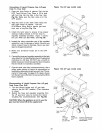
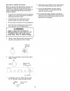
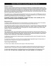
Z_WARNING
The location of the Burner Tube with respect
to the Orifice is vital for safe operation.
Check to ensure the Orifice is inside the
Burner Tube before using your gas grill. See
Fig. 2. If the Burner Tube does not fit over
the Valve Orifice, lighting the Burner may
cause explosion and/or fire.
Figure 2
GAS VALVE ASSEMBLY
ORIFICE BURNER TUBE
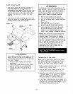
Figure 1 SPARK ELECTRODE AS- GAS COLLECTOR BOX
Ti(_ CLETAHNoBoUKRNERETUBE.............. 'o/_
HEAT-INSULATING RING BURNER TUBE COTTER PIN
28