


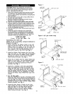
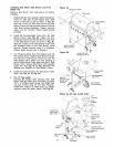
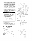
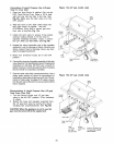
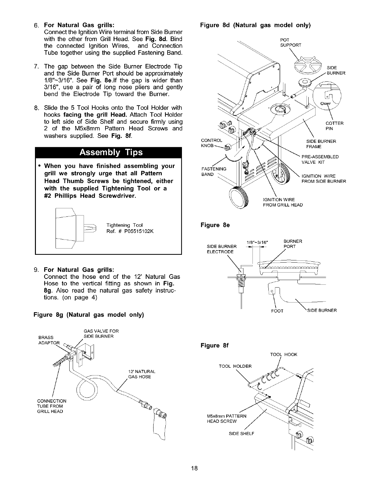
6. For Natural Gas grills:
Connect the Ignition Wire terminal from Side Burner
with the other from Grill Head. See Fig. 8d. Bind
the connected Ignition Wires, and Connection
Tube together using the supplied Fastening Band.
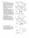
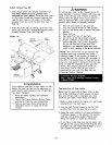
7. The gap between the Side Burner Electrode Tip
and the Side Burner Port should be approximately
1/8"~3/16''. See Fig. 8e.lf the gap is wider than
3/16", use a pair of long nose pliers and gently
bend the Electrode Tip toward the Burner.
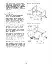
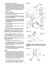
8. Slide the 5 Tool Hooks onto the Tool Holder with
hooks facing the grill Head. Attach Tool Holder
to left side of Side Shelf and secure firmly using
2 of the M5x8mm Pattern Head Screws and
washers supplied. See Fig. 8f.
• When you have finished assembling your
grill we strongly urge that all Pattern
Head Thumb Screws be tightened, either
with the supplied Tightening Tool or a
#2 Phillips Head Screwdriver.
Tightening Tool
Ref. # P05515102K
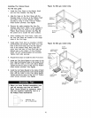
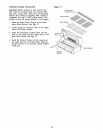
9. For Natural Gas grills:
Connect the hose end of the 12' Natural Gas
Hose to the vertical fitting as shown in Fig.
8g. Also read the natural gas safety instruc-
tions. (on page 4)
Figure 8g (Natural gas model only)
Figure 8d (Natural gas model only)
POT
SUPPORT
SIDE
COTTER
PIN
CONTROL SIDE BURNER
KNOB_ FRAME
VALVE KIT
FASTENING
BAND _ WIRE
FROM SIDE BURNER
IGNITION WIRE
FROM GRILL HEAD
Figure 8e
I/8"_3/16" BURNER
BRASS
ADAPTOR
GASVALVEFOR
SIDE BURNER
12'NATURAL
GAS HOSE
Figure 8f
TOOL HOLDER
TOOL HOOK
CONNECTION
TUBE FROM
GRILL HEAD
M5xSmm PATTERN
HEAD SCREW
SIDE SHELF
18