


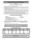

10
BROWN
WHITE
BLACK
WHITE (COM)
RED (LOW)
RED (LOW)
BLUE (MED)
BLACK (HI)
BLUE (MED)
BLACK (HI)
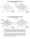
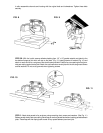
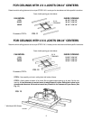
SHUTTER INSTALLATION
STEP 6 - Unpack shutter and read instructions included. Carefully follow these instructions to adjust the
spring tension on your shutter. Make sure the shutter opens and closes freely.
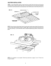
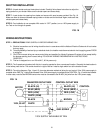
STEP 7 - Insert shutter into opening from below and secure with wood screws provided. See Fig. 16.
Make sure there is clearance between spring holder on shutter and the fan blade. Again, make sure that
shutter opens and closes freely.
STEP 8 - Fan installation is now complete. With control in “OFF” position, turn on 120V power supply to
fan. Test run fan through all speeds.
FIG. 16
WIRING INSTRUCTIONS
STEP 1 - PRECAUTIONS: READ CAREFULLY BEFORE WIRING FAN !
A. Electrical connections and all wiring should be done in accordance with the National Electrical Code and all local codes
that may apply.
B. To avoid possibility of serious injury or electrical shock, the installer must disconnect electric circuit supplying power PRIOR
to wiring fan.
C. CAUTION: Incorrect wiring can cause motor failure and possible fire. Marley Engineered Products will not accept liability
for damage resulting from incorrect wiring. FOLLOW ALL WIRING DIAGRAMS AND ALL INSTRUCTIONS
CAREFULLY.
D. This fan is designed to run on 120 volt A.C., 60 Hz power only.
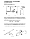
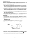
STEP 2 - The 3-speed control packed with this fan is used to operate fan from a remote wall location. Generally the best location is
in the hallway near the fan. The control should be in sight of the fan. Install a single switch box at the location chosen.
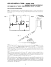
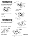
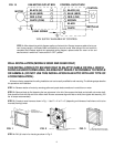
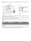
STEP 3 - The wiring diagrams, Figs. 14 and 15, show two alternate methods of wiring fan and control. If the 120V power supply is
available at the FAN, Fig. 14 should be followed. If the 120V power supply is available at the CONTROL, Fig. 15 should be followed.
In either case, note that the BROWN control wire must be connected to the BLACK (hot) wire from the 120V power supply.
FIG. 14
FAN MOTOR OUTLET BOX CONTROL OUTLET BOX
GND. SCREW
CONTROL
120V, 60 HZ
120V SUPPLY AVAILABLE AT FAN
MOTOR