


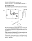
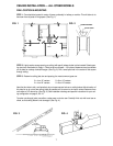

11
120V, 60 HZ
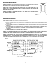
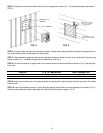
FIG. 15
FAN MOTOR OUTLET BOX CONTROL OUTLET BOX
GND. SCREW
BLACK (HI)
BLUE (MED)
MOTOR
RED (LOW)
BLACK (HI)
BLUE (MED)
RED (LOW)
WHITE (COM)
CONTROL
BLACK
BROWN
120V SUPPLY AVAILABLE AT CONTROL
WHITE
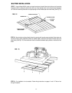
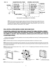
STEP 4 - After determining which diagram applies, pull wires to fan. Be sure to secure cable at fan to pre-
vent it being caught in the blade. Make connections to fan and control. After wiring of fan and control is
completed and checked against the appropriate wiring diagram, replace outlet box cover on fan and
secure control in switch box. Leave control in “OFF” position.
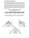
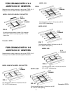
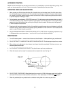
WALL INSTALLATION (MODELS 3038R AND 3638R ONLY)
THIS INSTALLATION IS TO BE USED ONLY IN AN ATTIC GABLE OR WALL WHICH
FACES AN UNOCCUPIED AREA, AN AREA NOT READILY ACCESSIBLE TO PEOPLE
OR ANIMALS. (DO NOT USE THIS INSTALLATION IN AN ATTIC WITH ANY TYPE OF
LOOSE INSULATION.)
All fans are factory assembled for ceiling installation and can be easily modified for wall mounting. The following steps describe
this procedure and installation.
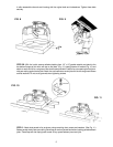
STEP 1—Reverse rotation of motor by reversing yellow and purple lead connections in conduit box on motor.
STEP 2—Remove blade by first loosening the two set screws in the hub. Now reverse the blade and reinstall onto motor shaft.
Hub should be flush with the end of the motor shaft. Be sure set screws align with flats on shaft, then tighten bolt securely (150
lbs. of torque recommended).
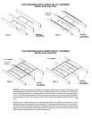
STEP 3—Construct wood frame as shown in Fig. 1. Use 2” x 4” or 2” x 6” (depending on thickness of wall where unit is to be
mounted) framing lumber.
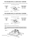
STEP 4—Drill (4) holes in fan housing as shown in Fig. 2.
“A”
SEE CHART
“B”
SEE
CHART
4” OR 6” —
DEPENDING ON
THICKNESS OF WALL
DRILL (4) - 1/4” HOLES - (1) IN CENTER OF EACH
FLANGE AS SHOWN.
SECURE SHUTTER IN PLACE
WITH WOOD OR LAG SCREWS
FIG. 1 FIG. 2 FIG. 3