


12
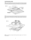
STEP 5—Position fan on frame and secure with (4) wood or lag screws (number 12 x 1 1/2” preferred) through holes drilled in
STEP 4.
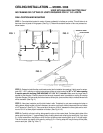
FIG. 4
FIG. 5
SEE
CHART
DOUBLE 2 X 6
HEADER
2 X 4 FRAMING
SECURE UNIT IN PLACE
WITH 2” X 2” FURRING
STRIPS INSIDE.
SECURE UNIT IN PLACE
OUTSIDE WITH MOULDING
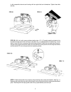
STEP 6—Unpack shutter and read the instructions included. Carefully follow these instructions to adjust the spring tension on
your shutter. Make sure the shutter opens and closes freely.
STEP 7—Stand assembly upright with motor at top and position shutter on outside of frame. Secure shutter with (8) wood or lag
screws (number 12 x 1” preferred) through holes in shutter frame. See Fig. 3.
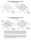
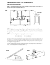
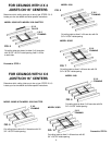
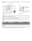
STEP 8—To mount this attic fan in gable or wall, a box must be framed into wall construction as shown in Fig. 4. See wall open-
ing in chart.
STEP 9—Insert frame containing fan and shutter assembly into opening with outside surface of shutter frame flush with outside
surface of wall.
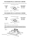
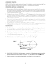
STEP 10—Nail frame assembly securely in place. Moulding may be used outside to improve appearance, as shown in Fig. 5.
Caulk around moulding to provide a water-tight seal. Follow wiring instructions on pages 11 & 12.
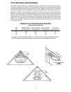
FAN SIZE “A” & “B” DIMENSIONS WALL OPENING SIZE
30” 33 3/4” x 33 3/4” 34” x 34”
36” 39 3/4” x 39 3/4” 40” x 40”