


130
ESPAÑOL
- página 7
ENGLISH
- page 1
6
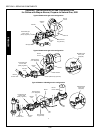
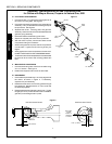
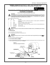
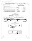
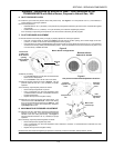
5. The pilot pressure should be adjusted as follows:
The current flow between the pilot hood and the
flame sensor, when measured with a microamp
meter or multimeter, holds constant at a minimum
of 2.0 µA. See Figure 7.
The pilot pressure as shown on the manometer is in
the range of 3-1/2 - 4 W.C. (8.7-10.0 mbar).
Adjust the pilot pressure as necessary by turning the
pilot adjustment screw on the combination gas control
valve. Turning the screw clockwise decreases the pilot
pressure. Turning the screw counter-clockwise increases
the pressure.
Some valves may have a burr in the pilot adjustment
portal. If you have fully tightened the adjustment screw,
and the manometer still does not register a change in
pressure, continue to tighten the screw to break through
the burr. Back the screw out until its top is flush with the
top of its hole, then tighten the screw again as necessary
to adjust the pressure. Repeat this procedure as
necessary to properly adjust the pilot pressure.
If the pilot pressure cannot be properly adjusted, switch
the oven off and allow it to cool; then, replace the
combination gas control valve. Repeat Section VII (Gas
Leak Test) before attempting to adjust the pilot pressure
again.
7. After the pilot pressure has been properly adjusted,
replace the cap screw.
8. Reset the ovens set point temperature to the customers
original settings. Leave the oven in operation to allow
the manifold pressure to be checked in the next Section
of these instructions.
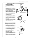
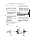
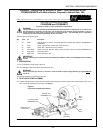
X. MANIFOLD PRESSURE ADJUSTMENT
1. Remove the regulator cap screw from the combination
gas control valve.
2. Using a manometer, check the pressure at the manifold
pressure tap, as shown in Figure 6. A manifold pressure
of 3-1/2 W.C. (8.7mbar) is recommended for natural
gas operation.
3. Adjust the pressure as necessary by turning the
adjustment screw on the combination gas control valve.
Turning the screw clockwise decreases the pressure.
Turning the screw counter-clockwise increases the
pressure.
If the manifold pressure cannot be properly adjusted,
switch the oven off and allow it to cool; then, replace the
combination gas control valve. Repeat Section VII (Gas
Leak Test) before attempting to adjust the manifold
pressure again.
4. After the manifold pressure has been properly adjusted,
replace the cap screw. Record the final value on the Gas
Conversion Label, as shown in Figure 8.
5. Switch the oven off, and allow it to cool.
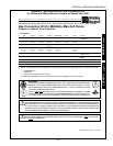
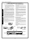
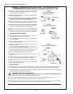
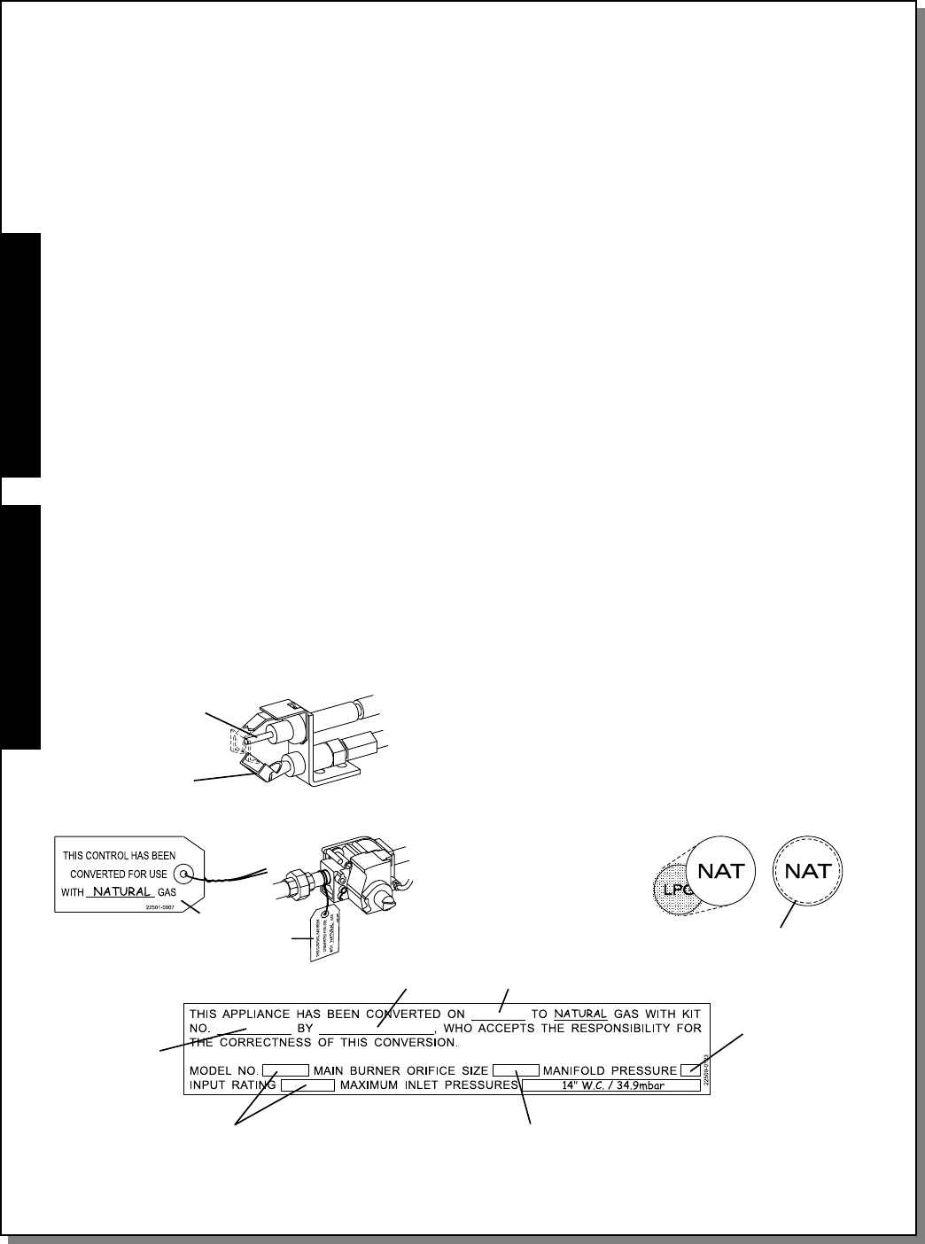
XI. MARKING AND LABELING
1. Print the word NATURAL in the space provided on the
Gas Control Conversion Tag, P/N 22501-0007. See
Figure 8. Fasten the tag onto the gas piping next to the
combination gas control valve.
2. Locate the round LPG label (red) on the burner or
burner motor. Attach the kit-supplied yellow/green
NAT label, P/N 22500-0064, on top of the LPG label.
The new label should completely cover the LPG label.
See Figure 8.
3. Complete the information on the Gas Conversion Label
as shown in Figure 8.
4. Attach the Gas Conversion Label in plain view on the
outside of the oven, as close as possilble to the ovens
serial plate.
Figure 8
Attach to gas
piping next to
combination
gas valve
Attach on top of
existing LPG
label (on burner or
burner motor)
Date of
conversion
Measured value
from Section X
See chart on
Page 1
Stated on the ovens
serial plate
Part no. of this
Kit - see chart
on Page 1
Name of
technician
Attach completed label in plain
view near serial plate
New label completely
covers LPG label
Figure 7
Pilot hood ( - )
Flame sensor ( + )
SECTION 3 - SERVICING COMPONENTS
Appendix - Instructions for All Gas Conversion Kits
for Ovens with Wayne Burner, Propane to Natural Gas, 8/00