49
C. WIRING
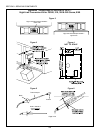
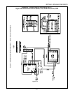
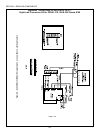
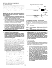
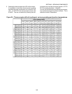
For the various wiring connections listed below, cut the kit-supplied #18 AWG wires to length. Refer to
Figures 7 and 8 (on pages 6 and 7) for diagrams of the wiring connections.
Lighted Reset Switch Wiring and Installation
14. Using the kit-supplied 1/4 wire connectors, connect the following kit-supplied wires:
- Red wires ................. connect one wire to each RESET terminal on the high limit control
- Black wire ................. connect to terminal NC on the high limit control
- White wire................. connect to terminal L2 on the ovens temperature controller
15. Slip the free ends of these four wires through the circular hole in the reset switch mounting bracket, so
that they hang down in front of the control compartment.
16. Use the kit-supplied 1/4 wire connectors to connect these four wires to the terminals on the lighted
reset switch.
- Terminals 1 and 3..... Red wires (these connections are interchangeable)
- Terminal 2 ................ Black wire
- Terminal 4 ................ White wire (kit-supplied)
17. Push the lighted reset switch through the mounting hole in the center of the bracket until it snaps into
place. Be sure to avoid pinching the wires against the sides of the mounting hole.
Cooldown circuit wiring
NOTE: Perform steps 18 and 19 ONLY if you are replacing a UE Type 55 controller. If you are
replacing a UE Type 54 controller (which has no cooldown circuit), skip ahead to Step 20.
18. Attach the ovens
existing cooldown wiring to the following terminals on the ovens Temperature Con-
troller, as shown in Figures 7 and 8.
For Ovens with a Digital Temperature Controller:
a. Terminal 9 ................ Black wire (from blower switch)
b. Terminal 10 .............. Brown wire (from blower switch)
For Ovens with an Analog Temperature Controller:
a. Terminal 13 .............. Black wire (from blower switch)
b. Terminal 14 .............. Brown wire (from blower switch)
19. Attach a brown kit-supplied wire between the following terminals on the Temperature Controller:
Digital Controller ............. Terminals 10 and L1
Analog Controller............ Terminals 13 and L1
High Limit Control wiring
20. Using the kit-supplied 1/4 wire connectors, wire the high limit control terminals as follows:
a. Terminal NO........... Purple wire (originally to UE control)
c. Terminal TC + ........ White wire (to thermocouple) - DO NOT CUT THIS WIRE TO LENGTH.
d. Terminal TC - ......... Red wire (to thermocouple) - DO NOT CUT THIS WIRE TO LENGTH.
f. Terminal L2 ............ White wire (kit-supplied; to neutral on the ovens terminal block)
h. Terminal COM ........ Orange wire (originally to UE control)
21. Using a 1/4 wire connector, attach a brown kit-supplied wire to the L1 terminal on the high limit
control. Attach the free end of the wire to the L1 terminal on the temperature controller.
Page 4 of 8
SECTION 3 - SERVICING COMPONENTS
Appendix - Instructions for Service Kit 39733 -
High Limit Conversion Kit for PS300, 310, 350 & 360 Ovens, 5/99


