


58
3
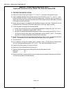
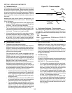
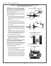
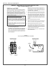
PS360 Series rear wall thermocouples -
before 2/96, serial numbers before ASH-0001
Thermocouples on these ovens are located on the rear wall
of the baking chamber. They are secured in place by a
clamp on the outside of the oven.
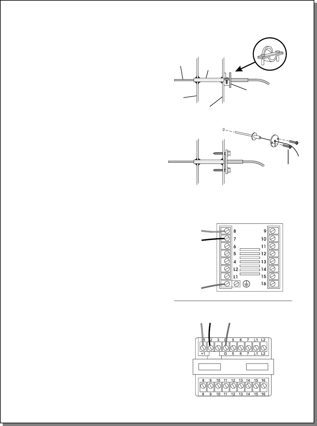
This Kit eliminates the clamp. The flange of the new ther-
mocouple is held to the back wall of the oven by a retaining
plate, as shown in Figure 3.
1. Loosen the retaining clamp and pull the thermocouple
straight out. Disconnect the thermocouple leads. Care-
fully thread the wiring out of the oven and discard the
thermocouple.
2. Remove and discard the cable clamp.
3. Slide the new thermocouple into the mounting tube until
the flange is seated firmly on the back wall of the oven.
4. Install the kit-supplied retaining plate (P/N 41687) as
shown in Figure 3.
5. Fasten the attachment plate to the back wall of the
oven using the two kit-supplied #10-16 x 3/4 self-tap-
ping screws. Ensure that the thermocouple flange is
securely trapped between the plate and the rear wall of
the oven.
6. Route the wiring through the grommet hole and into the
machinery compartment. Check that the leads are clear
of all components, PARTICULARLY THE BLOWER
MOTOR, by using the existing wiring bundles.
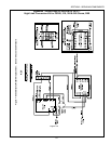
7. Connect the leads as shown in Figure 4.
8. Attach the kit-supplied nylon clamp and #10-16 x 3/4
screw to the rear of the oven. The clamp should be
positioned to support the thermocouple leads away from
the flue pipes and vent openings.
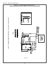
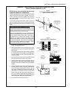
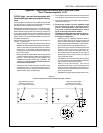
PS360 Series rear-wall thermocouples - 2/96
or later, serial numbers after ASH-0001
Thermocouples on these ovens are mounted directly to the
back wall of the oven using a single retaining screw. It
should be possible to simply replace the existing thermo-
couple using the original mounting hardware.
To replace the thermocouple:
1. Remove AND RETAIN the screw that holds the thermo-
couple in place on the rear wall.
2. Disconnect the thermocouple leads. Carefully thread
the wiring out of the oven and discard the thermocouple.
3. Slide the new thermocouple into the mounting tube until
the flange is seated firmly on the back wall of the oven.
4. Fasten the thermocouple to the back wall of the oven
using the original mounting screw. Then, perform Steps
6-8 of the preceding section to wire the thermocouple.
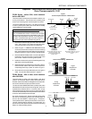
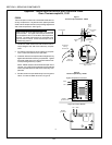
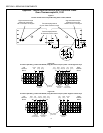
Figure 3
Thermocouple Installation - PS360 Series
Thermocouple
Mounting
tube
(welded to
plenum)
Oven
wall
Plenum
wall
Clamp (remove
and discard if
present)
Thermocouple
flange
Retaining
plate
New
thermocouple
#10-16 x 3/4
mounting
screws (2)
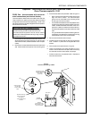
Figure 4
Thermocouple Wiring - PS360 Series
Digital Temperature Controller
Analog Temperature Controller
Red
White
Shielded
ground lead
RedWhite
Shielded
ground lead
Appendix - Instructions for Service Kits 33984 and 33985 -
Oven Thermocouple Kit, 11/01
SECTION 3 - SERVICING COMPONENTS