


70
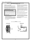
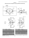
5. Early-style PS200 bearing replacement and alignment
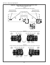
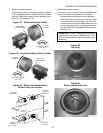
NOTE: This procedure is for early-style indirect fan
shaft assemblies only, as shown in Figure 25. Bearing
replacement procedures for the current-style indirect
fan shaft assembly (Figure 26) are provided on Page
72.
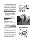
NOTE: The bracket assembly is designed for slight up
and down and right to left movement to attain free shaft
rotation when the shaft alignment tool is in place. Once
free shaft rotation is achieved, tighten all eight bracket
screws (Item 2).
11. Tighten rear flange bearing block screws (Item 11)
then front flange bearing block screws.
12. Remove shaft alignment tool, then recheck fan shaft
for free rotation.
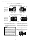
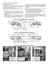
13. Install pulley (Item 8) on fan shaft and position fan
shaft per the dimensions shown in Figure 32. Align
the two flats per bearing which are machined on
fan shaft for the bearing set screws. Use High
Temperature Loctite, RC 620 on bearing set screws
and then tighten set screws. Recheck fan shaft for
free rotation.
14. Apply anti-seize compound on fan shaft before in-
stalling fan blade (Item 13). Position fan blade per
dimension shown in Figure 32.
15. Apply High Temperature Loctite Type RC 620 to
fan blade set screws.
NOTE: Tighten the two set screws on fan blade per
the following sequence when viewing fan blade from
front: first, the screw at the 12:00 position, then the
screw at the 3:00 position.
16. Recheck fan shaft rotation before installing back
wall to oven cavity.
NOTE: Apply anti-seize compound (MM P/N 17110-
0017) to all 12 bolts before installing back wall assem-
bly to oven.
17. Install back wall on oven.
18. Install fan belt.
NOTE: Excessive fan belt tension will create overload-
ing of rear bracket fan shaft bearing. Refer to Blower
Belt Tension on Page 69.
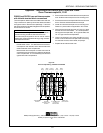
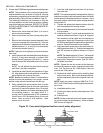
IMPORTANT: Before attempting any repair on the
early-style PS200 Indirect Fan Drive Assembly:
If you need to perform any maintenance more
involved than replacing and aligning the shaft bear-
ings, you should upgrade the fan shaft assembly
to the current version.
Check the front and rear brackets (Item 6 in Fig-
ure 32). If the brackets ARE NOT welded to-
gether, you should upgrade the fan shaft assem-
bly to the current version.
In either of these cases, you can upgrade the fan
shaft assembly using Service Kit P/N 49810-0121.
See Part Number Reference on Page 68 for details.
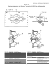
The following procedures are necessary to align the
fan shaft whenever service to the fan shaft or replace-
ment of the bearings is required. REFER TO FIGURE
32 FOR ILLUSTRATIONS OF THE COMPONENTS DE-
SCRIBED HERE.
1. Remove the entire back wall (Item 1) of oven to
service the fan assembly.
2. Remove the blower fan (Item 13) and pulley (Item
8).
NOTE: If parts are to be replaced, you should replace
them now.
3. When installing the Drive Bracket Assembly (Item
5) insert one 3/8 flat washer (Item 4) at the 4 outer
holes and one 3/8 special flat washer (Item 14) at
the 4 inner holes between bracket and back wall at
mounting locations. Use eight 3/8-16 x 1 screws
(Item 2) and assemble a 3/8 lockwasher (Item 3)
and a 3/8 flat washer (Item 4) onto each screw.
Insert a screw at all 8 locations, hand tighten only
at this time.
4. Install front and rear fan shaft flange bearings (Item
10), if they were removed, to Indirect Drive Bracket
(Item 6) using three 1/4-20 x 3/4 screws (Item 11)
and three 1/4 lockwashers (Item12) on each bear-
ing.
IMPORTANT: The bearings (10) must be mounted
so the grease fitting faces up when the bracket
assembly (Item 5) is mounted on the rear wall.
NOTE: Do not tighten flange bearing block screws
until Step 10 has been completed.
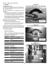
9. Install the fan shaft as shown in Figure 32. Align
bearing set screws with flats on shaft but do not
tighten set screws at this time.
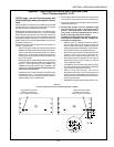
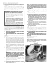
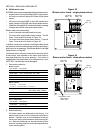
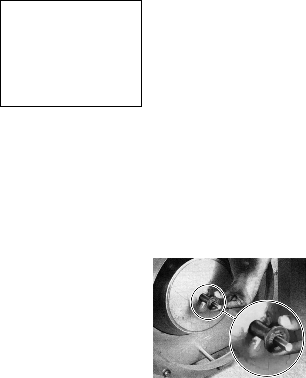
10. Insert fan shaft alignment tool (Item 15) into back
wall as shown in Figure 31.
Figure 31
Fan shaft alignment tool
SECTION 3 - SERVICING COMPONENTS