


93
SECTION 3 - SERVICING COMPONENTS
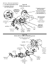
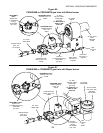
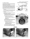
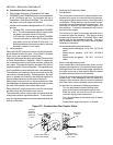
D. Pilot/Ignitor Assembly
The pilot assembly is attached to the end of the pilot line.
It consists of an ignitor electrode/flame sensor, a pilot shield
and the pilot burner. See Figure 63.
The pilot assembly includes a safety circuit. An electrical
current is sent to the flame sensor probe to prove the pres-
ence of the pilot flame. When the spark ignites the pilot, a
circuit is completed THROUGH THE FLAME from the flame
sensor probe to the pilot burner, which is grounded. This
safety circuit must be completed before the pilot will light.
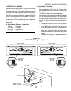
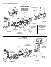
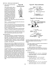
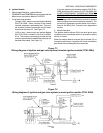
1. Pilot Shield
The pilot shield is a plate located on the bottom of the
pilot. It prevents drafts, etc. from blowing the pilot flame
away from the sensing probe. See Figure 64.
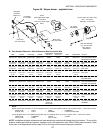
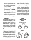
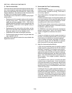
2. Flame target
The flame target aids in distributing the flame from the
end of the venturi. See Figure 65.
PS310/360-series ovens built prior to 6/87 are not
equipped with a flame target. The burner on these
ovens resembles the one shownin Figure 64.
The angled flame target is used on:
- PS200-series ovens built through 3/02.
- PS310, PS314, PS360 and PS360WB ovens
built 6/87 or later.
- PS570S ovens.
All of these ovens use a 120V burner blower motor.
Most units equipped with the 120V burner blower
motor also use the angled flame target.
The round flame target is used on:
- PS200-series ovens built 4/02 or later.
- PS360EWB and PS360WB70 ovens equipped
with the Wayne burner system.
- PS555 and PS570G ovens.
All of these ovens use a 208/240V burner blower
motor. All ovens equipped with the line voltage
burner blower motor use the round flame target.
Figure 63 - Pilot/ignitor assembly
Pilot
burner
Ignitor/sensor
probe
Pilot line
connects here
Spark cable
connects here
Figure 64
End of burner without flame target
showing pilot shield
Figure 65
Flame targets
Pilot
shield
Angled
target
Round
target
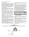
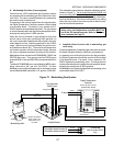
Hood