


11
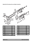
Models 8751/8754 Important: To the Operator
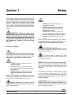
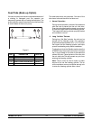
Symbol Definitions
To better communicate in the International arena,
symbols have replaced words on many of our operator
switches, function, and fault indicators. Your Taylor
equipment is designed with these International
symbols.
The following c hart i dentifies the symbol definitions.
=OFF
=ON
=MIX
= STANDBY
= WASH
=AUTO
=PUMP
Power Switch
When placed in the ON position, the power switch
allows SOFTECH control panel operation.
Indicator Lights
Located on the front of the machine is a mix level
indicating light. When the light begins to flash, it
indicates that the mix hopper has a low supply o f mix
and should be refilled as soon as possible. Always
maintain at least 3” (76 mm) of mix in the hopper. If you
neglect to add mix, a freeze-up may occur. This will
cause eventual damage to the beater , blades, drive
shaft, and f reezer door.
MIX REF Key
When the MIX REF key is pressed, the light comes on
indicating the mix hopper refrigeration system is
operating. For the Model 8754 the MIX REF is
controlled by the left side of the freezer as viewed from
the operator end. The MIX REF function cannot be
cancelled unless the AUTO or STA NDBY modes are
cancelled first.
STANDBY Key
The Separate Hopper Refrigeration System (SHR)
and the Cylinder Temperature Retention System
(CTR) are standard features. The SHR incorporates
the use of a separate small refrigeration system to
maintain the mix in the hopper below 40_(4.4_C) to
assure bacteria control. The CTR works with the SHR
to maintain a good quality product. During long “No
Sale” periods, it is necessary to warm the product in
the freezing cylinder to approximately 35_Fto40_F
(1.7_Cto4.4_C) to prevent overbeating and product
breakdown.
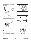
To activate the SHR and CTR, press the ST ANDBY
key. Remove the air orifice and place the air tube (end
without the hole) into the mix inlet hole.
When the ST ANDBY key is pressed, the light comes
on, indicating the CTR (Cylinder Temperature
Retention System) has been activated. In the
STANDBY mode, the WASH and AUTO functions are
automatically cancelled. The MIX REF function is
automatically locked in to maintain the mix in the
hopper.
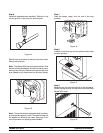
To resume normal operation, press the AUTO key.
When the unit cycles off, the product in the freezing
cylinder will be at s e rving viscosity. At this time, place
the air tube (end with the hole) into the mix inlet hole
and install the air orifice.