


17
Models 8751/8754 Operating Procedures
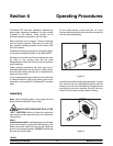
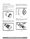
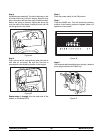
Step 6
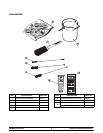
Install the adjustable draw handle(s). Slide the o-ring
into the groove on t he pivot pin, and lubricate.
Figure 14
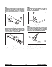
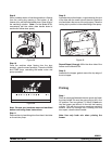
Slide the fork over the bar in the slot of the draw valve.
Secure with p ivot pin.
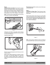
Note: The Model 8754 has three draw handles. Slide
the fork of the draw handle in the slot of the draw valve,
starting from the right. Slide the pivot pin through each
draw handle as you insert them into the draw valves.
Figure 15
Note: These units feature adjustable draw handles to
provide the best portion control. The draw handles can
be adjusted for different flow rates. See page 12 for
more information on adjusting these handles.
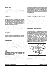
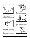
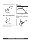
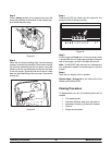
Step 7
Snap the design cap(s) over the end of the door
spout(s).
Figure 16
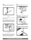
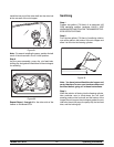
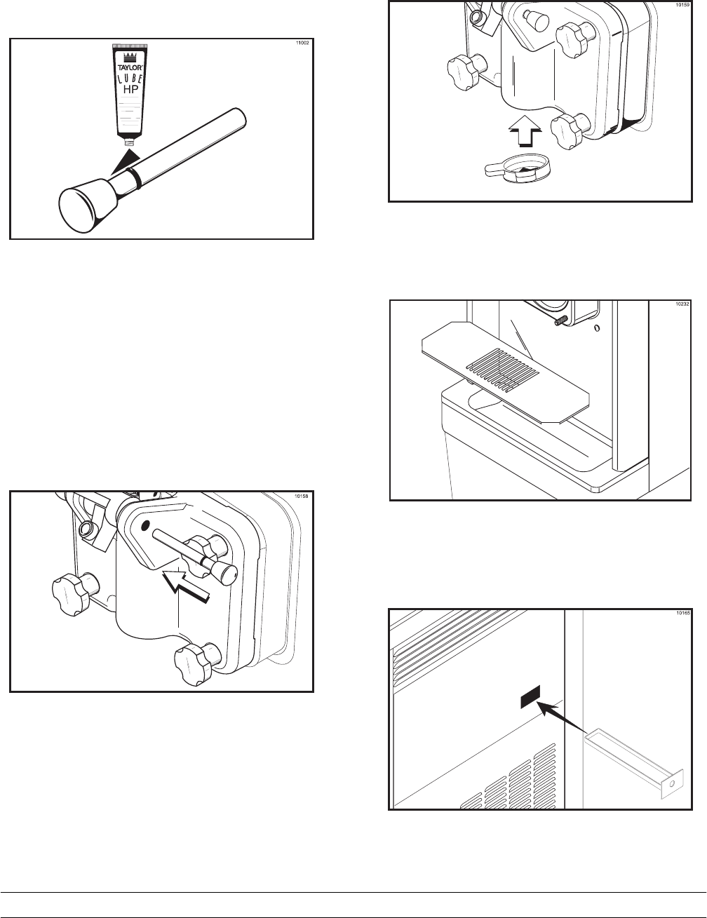
Step 8
Install the front drip tray and the splash shield under
the door s pout(s).
Figure 17
Step 9
Slide the rear drip pan into the hole in the side panel.
Slide the pump drip pan into the hole in the back panel
(Model 8751 only).
Figure 18