


19
Models 8751/8754 Operating Procedures
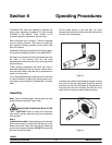
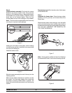
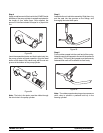
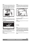
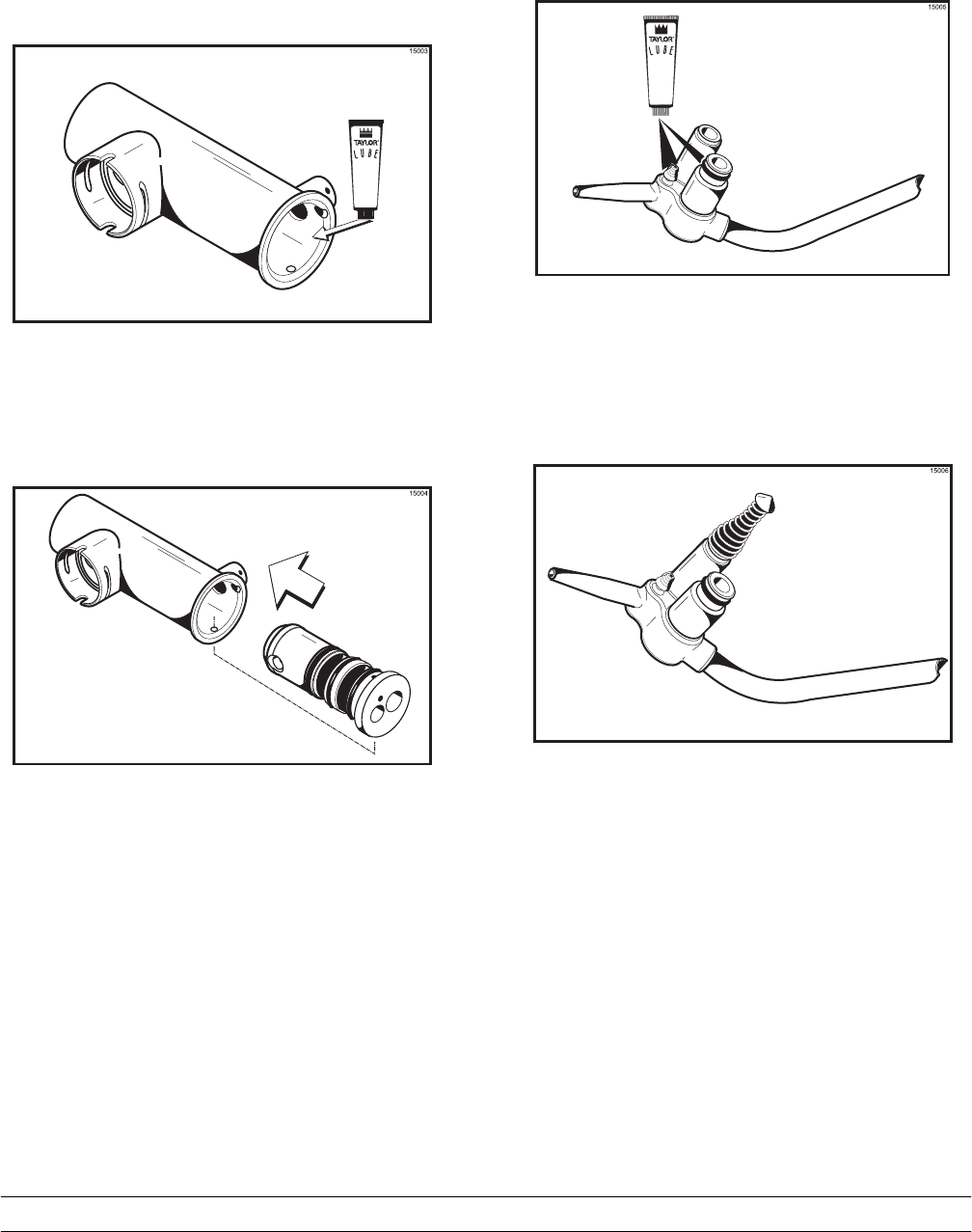
Step 4
Apply asmallamount of lubricant to the LOWER inside
diameter of the pump cylinder to a depth equivalent to
the l ength of your index finger. Once applied, the
amount of lubricant should be equal to a paper-thin
film.
Figure 23
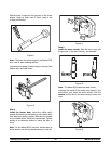
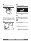
Insert the assembled piston and liquid valve body into
the pump cylinder and push upwards. Align the steel
button at the base of the valve body with the cut-out
groove at the bottom of the pum p cylinder.
Figure 24
Note: The hole in the piston must be visible through
the drive hole in the pum p cylinder.
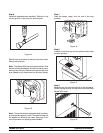
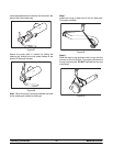
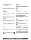
Step 5
Assemble the mix inlet tube assembly. Slide the o-ring
and the seal into the grooves on the fittings, and
thoroughly lubricate these par ts.
Figure 25
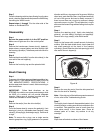
Step 6
Put the rubber poppet into the small end of t he spring.
Attach the springand poppet tothe end of the p ressure
relief fitting. The spring and poppet must be securely
fastened and must not be allowed to f loat freely.
Figure 26
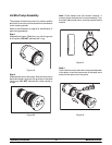
Note: Therubber poppet andspring act as apressure
relief valve to prevent a pressure build up in the
freezing c ylinder.