


16
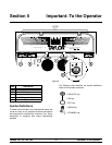
Models 150, 152, 162, 168Important: To the Operator
090526
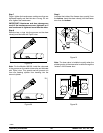
Reset Button
If an overload condition occurs, the freezer will
automatically stop operating. To properly reset the
freezer, place the toggle switch in the “ OFF” position.
W ait two or three minutes; then press the reset button.
Place the power switch in the “W ASH” position and
observe the freezer’s performance; place the power
switch in the “AUTO” position.
Note: If the freezer is unplugged from the wall
receptacle, it will be necessary to press the reset
button for the freezer to operate once power is
re- established.
Power Switch
The center position is “OFF”. The left position is
“WASH” which activates the beater motor only. The
right position is “AUTO”, which activates the beater
motor and the refrigeration system.
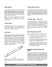
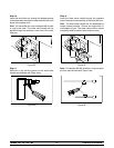
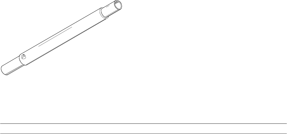
Feed Tube
The models 150, 152, 162 and 168 ar e called upon to
handle a large variety of products (i.e., soft serve,
yogurts, Italian ices, sherbets, etc.). Thus, the
consistency of the mix you use will vary. The feed tube
meters a combination of mix and air i nto the freezing
cylinder. If not enough mix enters the freezing cylinder,
a freeze- up may occur, which will cause eventual
damage to the beater . Depending upon the product
being run, you may wish to contact your local
authorized Taylor Distributor to m ake a slight
adjustment in the feed tube.
Figure 10
Note: During “AUTO” operation, the orifice end of the
tube should be i nserted i n the hole in the hopper.
Taylor Quality Control
These units use a solid state control called the T.Q.C.
The purpose of this solid state control i s to s ense the
viscosity (thickness) of the product in the freezing
cylinder. With the power switch in the “AUTO” position,
the T.Q.C. will automatically keep the mix in the
freezing cylinder at the proper viscosity and ready for
serving.
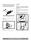
Indicator Light - “Mix Low”
A mix level indicating light is located at the front of the
unit. When the light is on, it indicates that the mix
hopper has a low supply of mix and should be refilled
as soon as possible. Always maintain at least 2” (5.1
cm) of mix in the hopper. If you neglect to add mix, a
freeze- up may occur. This will cause eventual
damage to the beater as sembly and to the freezer
door.
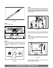
Mix Refrigeration Switch
The mix refrigeration switch is located under the
control c hannel and is used for several purposes:
1. For the unit to operate in the “AUTO” mode, the
mix refrigeration s witch m ust be “ON”.
2. For the separate hopper refrigeration system to
operate, the mix refrigeration switch must be in
the “ON” or the “STANDBY” position.
3. For the cylinder temperature retention system to
operate, the power switch must be in the “AUTO”
position and the mix refrigeration switch must be
in t he “ST ANDBY” pos ition.
Separate Hopper Refrigeration
(SHR)
This feature incorporates the use of a separate small
refrigeration system to chill (on a limited basis) and to
maintain t he mix in the hopper to under 40_F(4.4_C)
and assures bacterial control. To activate this system,
place the power switch in the “AUTO” position and the
mix refrigeration s witch in the “ ON” pos ition. To oper-
ate this system in the “STANDBY” mode, place the
power switch in the “AUTO” position and the mix refri-
geration switch in the “STANDBY” position.