23
Models 150, 152, 162, 168 Operating Procedures
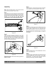
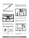
Figure 31
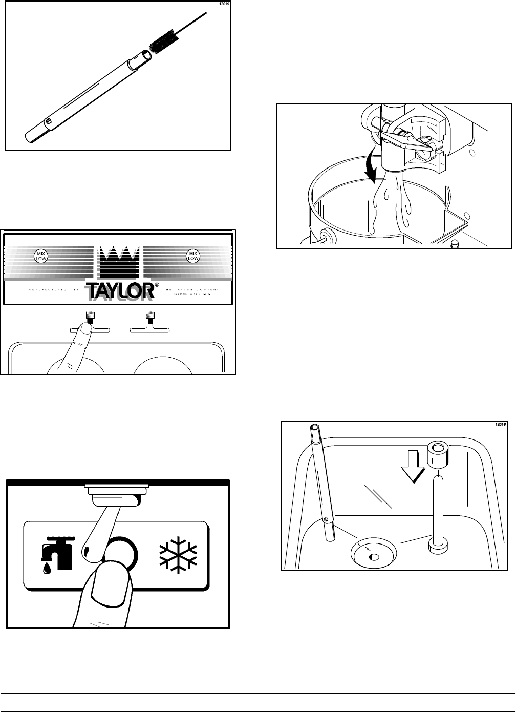
Step 4
Press the reset button.
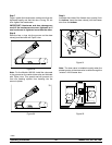
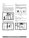
Figure 32
Step 5
Place the power switch in the “W ASH” position. This
will cause the sanitizing solution in the freezing
cylinder to be agitated. Allow it to agitate for five
minutes.
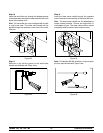
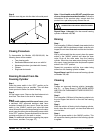
Figure 33
Step 6
Place an empty pail beneath the door spout and raise
the draw valve. Draw o f f all of the sanitizing solution.
When the sanitizer stops flowing from the door spout,
lower the draw valve and place the power switch in the
“OFF” pos ition.
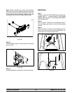
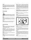
Figure 34
Note: On Models 162/168, momentarily pull down the
center dr aw handle to sanitize the center door spout.
Step 7
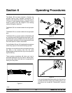
With sanitized hands, stand the feed tube in the corner
of the mix hopper. Place the mix level float on the mix
level float stem.
Figure 35
Repeat Steps 1 through 7 for the second freezing
cylinder on Models 162/168.


