


2
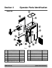
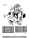
Models 358 & 359To the Installer
110318
Air Cooled Units
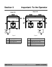
DO NOT obstruct air intake and discharge openings:
Air cooled units require a minimum of 3” (76 mm) of
clearance around all sides of the freezers and 3-1/2”
(89 mm) on the bottom.
Model 359 only: Installation of air deflector is
required.
Failure to allow adequate clearance can reduce the
refrigeration capacity of the freezers and possibly
cause permanent damage to the compressors.
Electrical Connections
In the United States, this equipment is intended to
be installed in accordance with the National
Electrical Code (NEC), ANSI/NFPA 70-1987. The
purpose of the NEC code is the practical
safeguarding of persons and property from hazards
arising from the use of electricity. This code contains
provisions considered necessary for safety. In all
other areas of the world, equipment should be
installed in accordance with the existing local codes.
Please contact your local authorities.
FOLLOW YOUR LOCAL ELECTRICAL CODES!
Each freezer requires one power supply for each
data label on the freezer. Check the data label(s) on
the freezer for branch circuit overcurrent protection
or fuse, circuit ampacity and other electrical
specifications. Refer to the wiring diagram provided
inside the control box for proper power connections.
CAUTION: THIS EQUIPMENT MUST BE
PROPERLY GROUNDED! FAILURE TO DO SO
CAN RESULT IN SEVERE PERSONAL INJURY
FROM ELECTRICAL SHOCK!
This unit is provided with an equipotential
grounding lug that is to be properly attached to the
rear of the frame by the authorized installer. The
installation location is marked by the equipotential
bonding symbol (5021 of IEC 60417-1) on both the
removable panel and the equipment's frame.
S Stationary appliances which are not
equipped with a power cord and a plug or
another device to disconnect the appliance
from the power source must have an all-pole
disconnecting device with a contact gap of
at least 3 mm installed in the external
installation.
S Appliances that are permanently connected
to fixed wiring and for which leakage
currents may exceed 10 mA, particularly
when disconnected, not used for long
periods, or during initial installation, shall
have protective devices such as a GFI to
protect against the leakage of current,
installed by authorized personnel to the local
codes.
S Supply cords used with this unit shall be
oil-resistant, sheathed flexible cable, not
lighter than ordinary polychloroprene or
other equivalent synthetic
elastomer-sheathed cord (Code designation
60245 IEC 57) installed with the proper cord
anchorage to relieve conductors from strain,
including twisting, at the terminals and
protect the insulation of the conductors from
abrasion.
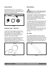
Beater Rotation
Beater rotation must be clockwise as
viewed looking into the freezing cylinder.
Note: The following procedures must be performed
by an authorized Taylor service technician.
To correct the rotation on a three-phase unit,
interchange any two incoming power supply lines at
the freezer main terminal block only.
To correct rotation on a single-phase unit, change
the leads inside the beater motor. (Follow the
diagram printed on the motor.)
Electrical connections are made directly to the
terminal block provided in the small junction box
located behind the left side panel on the bottom of
the frame.