


19
RLC-PRC016-EN
Application
Considerations
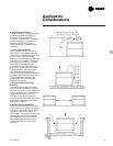
Typical Water Piping
All building water piping must be
flushed prior to making final connections
to the chiller. To reduce heat loss and
prevent condensation, insulation should
be installed. Expansion tanks are also
usually required so that chilled water
volume changes can be accommodated.
A typical piping arrangement is shown in
Figure A-1.
Short Water Loops
The proper location of the temperature
control sensor is in the supply (outlet)
water. This location allows the building
to act as a buffer and assures a slowly
changing return water temperature. If
there is not a sufficient volume of water
in the system to provide an adequate
buffer, temperature control can be lost,
resulting in erratic system operation and
excessive compressor cycling. A short
water loop has the same effect as
attempting to control from the building
return water.
The Air-Cooled Series R
™
70-125 ton
chiller has excellent leaving chilled water
control capabilities because of
exceptional controls, EXV and linear
unloading. However, it is still a good idea
to make sure the evaporator water loop
is sized sufficiently to help maintain
temperature control.
As a guideline, ensure the volume of
water in the evaporator loop equals or
exceeds two times the evaporator flow
rate. For a rapidly changing load profile,
the amount of volume should be
increased.
To prevent the effect of a short water
loop, the following items should be
given careful consideration:
A storage tank or larger header pipe to
increase the volume of water in the
system and, therefore, reduce the rate of
change of the return water temperature.
Multiple Unit Operation
Whenever two or more units are used
on one chilled water loop, Trane
recommends that their operation be
controlled from a single control device,
such as a Trane Tracer
™
system.
1. Series Operation
Some systems require large chilled
water temperature drops (16 to 24°F).
For those installations, two units with
their evaporators in series are usually
required. Control of the units should be
from a common temperature controller
to prevent the separate thermostats
fighting one another and continually
hunting. It is possible to control from the
two individual unit controls, but a
common temperature controller
provides a positive method for
preventing control overlap, more closely
matches system load, and simplifies
compressor lead-lag capability.
2. Parallel Operation
Some systems require more capacity or
standby capability than a single machine
can provide. For those installations, two
units with their evaporators in a parallel
configuration are typical. The only
effective way of controlling two units in
parallel is with a single temperature
controller. Two individual temperature
controllers are not capable of providing
reliable system control and will often
result in unsatisfactory operation.
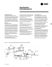
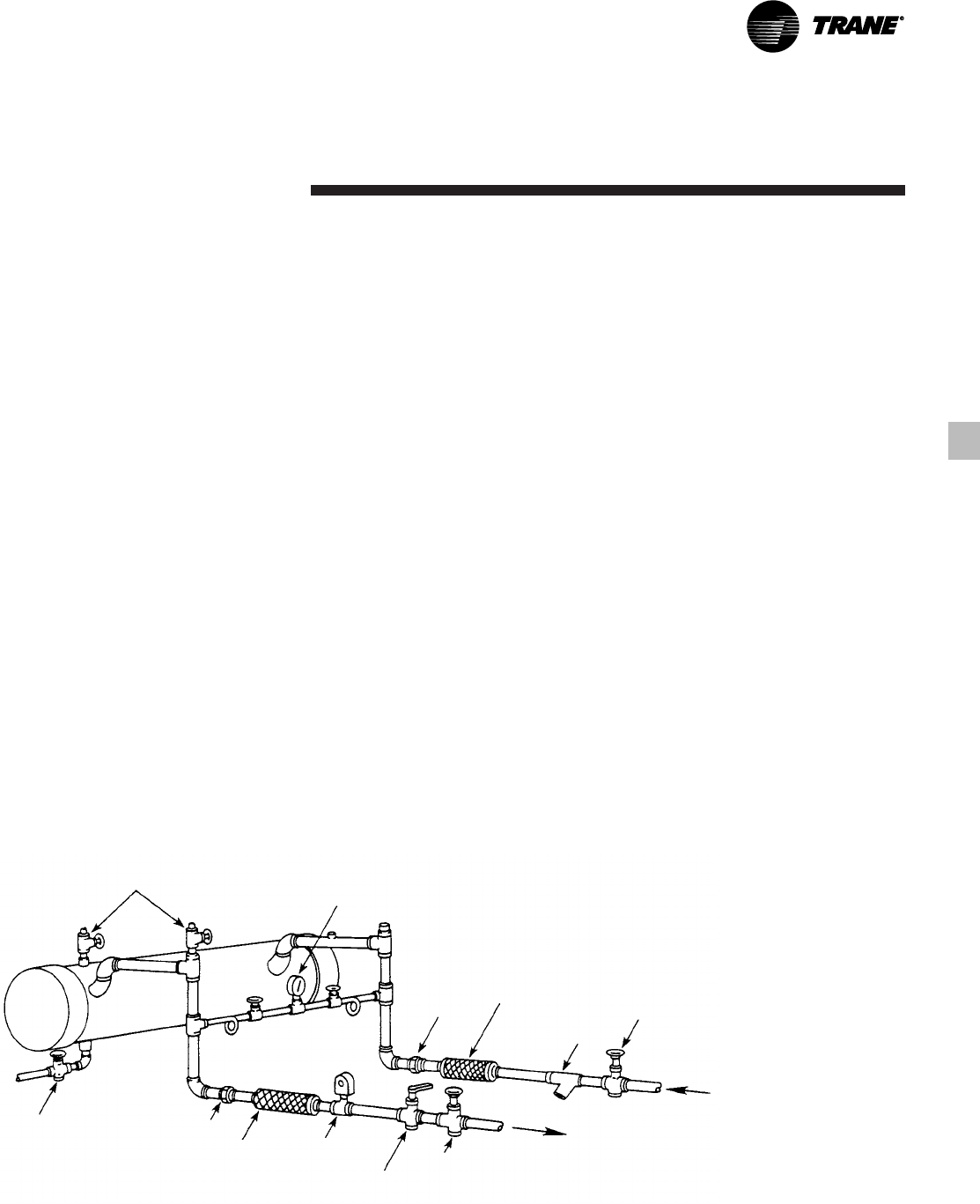
Figure A-1 — Recommended Piping Components For Typical Evaporator Installation
Vents
Valved
Pressure
Gauge
Drain
Union
Vibration
Eliminator
Flow
Switch
(Optional)
Balancing Valve
Gate Valve
Union
Water
Strainer
Vibration
Eliminator
Gate Valve