29
RLC-PRC016-EN
Electrical Data
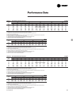
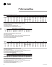
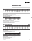
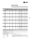
Table E-1 — Electrical Data (50 & 60 Hz, 3 Phase)
Unit Wiring Motor Data
Fans
Unit Rated # of Power Max. Fuse, HACR Rec. Time Compressor (Each) (Each) Control
Size Voltage (9)
Connections (1)
MCA (3) Breaker or MOP (2,11) Delay or RDE (4) Qty RLA (5) LRA (8) Qty. kW FLA kW (7, 10)
RTAA 70 200/60 1 300 400 350 2 115 - 115 800 - 800 8 1.0 5.1 0.75
230/60 1 265 350 300 2 100 - 100 690 - 690 8 1.0 5.0 0.75
380/60 1 163 200 200 2 61 - 61 400 - 400 8 1.0 3.2 0.75
460/60 1 133 175 150 2 50 - 50 330 - 330 8 1.0 2.5 0.75
575/60 1 108 125 125 2 40 - 40 270 - 270 8 1.0 2.2 0.75
380/50 1 140 175 150 2 53 - 53 308 - 308 8 0.7 2.5 0.75
400/50 1 133 175 150 2 50 - 50 325 - 325 8 0.7 2.5 0.75
415/50 1 128 175 150 2 48 - 48 337 - 337 8 0.7 2.5 0.75
RTAA 80 200/60 1 361 500 400 2 142 - 142 800 - 800 8 1.0 5.1 0.75
230/60 1 319 400 350 2 124 - 124 760 - 760 8 1.0 5.0 0.75
380/60 1 194 250 225 2 75 - 75 465 - 465 8 1.0 3.2 0.75
460/60 1 160 200 175 2 62 - 62 380 - 380 8 1.0 2.5 0.75
575/60 1 131 175 150 2 50 - 50 304 - 304 8 1.0 2.2 0.75
380/50 1 167 200 175 2 65 - 65 356 - 356 8 0.7 2.5 0.75
400/50 1 160 200 175 2 62 - 62 375 - 375 8 0.7 2.5 0.75
415/50 1 155 200 175 2 60 - 60 389 - 389 8 0.7 2.5 0.75
RTAA 90 200/60 1 428 600 500 2 192 - 142 990 - 800 9 1.0 5.1 0.75
230/60 1 378 500 450 2 167 - 124 820 - 760 9 1.0 5.0 0.75
380/60 1 230 300 300 2 101 - 75 497 - 465 9 1.0 3.2 0.75
460/60 1 190 250 225 2 84 - 62 410 - 380 9 1.0 2.5 0.75
575/60 1 154 200 175 2 67 - 50 328 - 304 9 1.0 2.2 0.75
380/50 1 195 250 225 2 88 - 65 386 - 356 9 0.7 2.5 0.75
400/50 1 190 250 225 2 84 - 62 402 - 375 9 0.7 2.5 0.75
415/50 1 182 250 225 2 81 - 60 417 -389 9 0.7 2.5 0.75
RTAA 100 200/60 1 483 600 600 2 192 - 192 990 - 990 10 1.0 5.1 0.75
230/60 1 426 500 500 2 167 - 167 820 - 820 10 1.0 5.0 0.75
380/60 1 259 350 300 2 101 - 101 497 - 497 10 1.0 3.2 0.75
460/60 1 214 250 250 2 84 - 84 410 - 410 10 1.0 2.5 0.75
575/60 1 173 225 200 2 67 - 67 328 - 328 10 1.0 2.2 0.75
380/50 1 223 250 250 2 88 - 88 382 - 382 10 0.7 2.5 0.75
400/50 1 214 250 250 2 84 - 84 402 - 402 10 0.7 2.5 0.75
415/50 1 208 250 250 2 81 - 81 417 - 417 10 0.7 2.5 0.75
RTAA 110 200/60 1 535 700 600 2 233 - 192 1190 - 990 10 1.0 5.1 0.75
230/60 1 471 600 600 2 203 - 167 1044 - 820 10 1.0 5.0 0.75
380/60 1 287 400 350 2 123 - 101 632 - 497 10 1.0 3.2 0.75
460/60 1 235 300 300 2 101 - 84 522 - 410 10 1.0 2.5 0.75
575/60 1 191 250 225 2 81 - 67 420 - 328 10 1.0 2.2 0.75
380/50 1 245 300 300 2 106 - 88 487 - 382 10 0.7 2.5 0.75
400/50 1 236 300 300 2 101 - 84 512 - 402 10 0.7 2.5 0.75
415/50 1 228 300 300 2 97 - 81 531 - 417 10 0.7 2.5 0.75
RTAA 125 200/60 1 576 800 700 2 233 - 233 1190 - 1190 10 1.0 5.1 0.75
230/60 1 507 700 600 2 203 - 203 1044 - 1044 10 1.0 5.0 0.75
380/60 1 309 400 350 2 123 - 123 632 - 632 10 1.0 3.2 0.75
460/60 1 253 350 300 2 101 - 101 522 - 522 10 1.0 2.5 0.75
575/60 1 205 250 225 2 81 - 81 420 - 420 10 1.0 2.2 0.75
380/50 1 264 350 300 2 106 - 106 487 - 487 10 0.7 2.5 0.75
400/50 1 253 350 300 2 101 - 101 512 - 512 10 0.7 2.5 0.75
415/50 1 244 350 300 2 97 - 97 531 - 531 10 0.7 2.5 0.75
Notes:
1. As standard, all 70-215 ton units require a single point power connection.
2. Max Fuse or HACR type breaker = 225 percent of the largest compressor RLA plus 100 percent of the second compressor RLA, plus the sum of the condenser fan
FLA per NEC 440-22. Use FLA per circuit, NOT FLA for the entire unit).
3. MCA - Minimum Circuit Ampacity - 125 percent of largest compressor RLA plus 100 percent of the second compressor RLA plus the sum of the condenser fans
FLAs per NEC 440-33.
4. RECOMMENDED TIME DELAY OR DUAL ELEMENT (RDE) FUSE SIZE: 150 percent of the largest compressor RLA plus 100 percent of the second compressor RLA
and the sum of the condenser fan FLAs.
5. RLA - Rated Load Amps - rated in accordance with UL Standard 1995.
6. Local codes may take precedence.
7. Control kW includes operational controls only. Does not include evaporator heat tape.
8. LRA - Locked Rotor Amps - based on full winding (x-line) start units. LRA for wye-delta starters is 1/3 of LRA of x-line units.
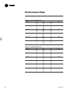
9. VOLTAGE UTILIZATION RANGE:
Rated Voltage Utilization Range
200 180-220
230 208-254
380 342-418
460 414-506
575 516-633
10. A 115/60/1, 15 amp customer provided power connection is required to operate the unit controls. A
separate 115/60/1, 15 amp customer provided power connection is also needed to power the evaporator
heat tape (420 watts @ 120 volts). If the optional control power transformer is used, the customer needs
only to provide a power connection for the evaporator heat tape.
11. If factory circuit breakers are supplied with the chiller, then these values represent Maximum Overcurrent
Protection (MOP).


