


33
RLC-PRC016-EN
Controls
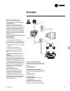
Simple Interface With Other Control
Systems
Microcomputer controls afford simple
interface with other control systems,
such as time clocks, building automation
systems and ice storage systems. Wiring
to the unit can be as simple as two
wires! This means you can have the
flexibility to meet job requirements while
not having to learn a complicated control
system.
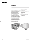
Safety Controls
A centralized microcomputer offers a
higher level of machine protection. Since
the safety controls are smarter, they limit
compressor loading to avoid
compressor or evaporator failures,
thereby minimizing nuisance shutdown.
The Unit Control Module (UCM) directly
senses the control variables that govern
the loading of the chiller: motor current
draw, evaporator temperature,
condenser temperature, etc. When any
one of the variables approaches a limit
condition where the unit may be
damaged or shutdown on a safety, the
UCM takes corrective action to avoid
shutdown and keep the chiller operating.
It does this through combined actions of
compressor slide valve modulation,
electronic expansion valve modulation
and fan staging. The UCM optimizes
total chiller power consumption during
normal operating conditions. During
abnormal operating conditions, the UCM
will continue to optimize chiller
performance by taking the corrective
action necessary to avoid shutdown.
This keeps cooling capacity available
until the problem can be solved.
Whenever possible, the chiller is allowed
to perform its function; make chilled
water. In addition, microcomputer
controls allow for more types of
protection such as over and under
voltage. Overall, the safety controls help
keep the building running and out of
trouble.
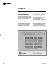
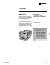
Monitoring And Diagnostics
Since the microcomputer provides all
control functions, it can easily indicate
such parameters as leaving chilled water
temperature and capacity stage.
If a failure does occur, one of over 90
individual diagnostic and operating
codes will be used to indicate the
problem, giving more specific
information about the failure. All of the
monitoring and diagnostic information is
displayed directly on a microcomputer
display.
Interface With The Trane Integrated
Comfort
™
System (ICS)
When the air-cooled Series R
™
chiller is
used in conjunction with a Trane Tracer
™
system, the unit can be monitored and
controlled from a remote location. The
air-cooled Series R
™
chiller can be
controlled to fit into the overall building
automation strategy by using time of
day scheduling, timed override, duty
cycling, demand limiting, and chiller
sequencing. A building owner can
completely monitor the air-cooled Series
R
™
chiller from the Tracer system, as all
of the monitoring information indicated
on the microcomputer can be read off
the Tracer system display. In addition, all
the powerful diagnostic information can
be read back at the Tracer system. Best
of all, this powerful capability comes
over a single twisted pair of wires!
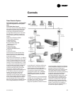
Air-cooled Series R
™
chillers can
interface with many different external
control systems, from simple stand-
alone units to ice making systems. Each
unit requires a single-source, three-
phase power supply and two 115-volt
power supplies. When an optional
control power transformer is used, a
single 115-volt supply handles the
evaporator heat tape. For basic stand-
alone applications, the interface with
outside control is no different than for
other Trane chillers. However, the RTAA
units have many features that can be
used to interface with building control
systems.
Standard Features
1. External Auto/Stop
A jobsite provided contact closure will
turn the unit on and off.
Note: Do not use the chilled water pump
to stop the chiller.
2. Chilled Waterflow Interlock
A jobsite provided contact closure from
a chilled water pump contactor or a flow
switch is required and will allow unit
operation if a load exists. This feature
will allow the unit to run in conjunction
with the pump system.
3. External Interlock
A jobsite supplied contact opening wired
to this input will turn the unit off and
require a manual reset of the unit
microcomputer. This closure is typically
triggered by a jobsite supplied system
such as a fire alarm.
4. Chilled Water Pump Control
Unit controls provide an output to
control chilled water pump(s). One
contact closure to the chiller is all that is
required to initiate the chilled water
system.
5. Remote Running and Alarm Indication
Contacts
The unit provides three single-pole/
double-throw contact closures to
indicate that a failure has occurred, if any
compressors are running, or if the
compressors are running at maximum
capacity. These contact closures may be
used to trigger jobsite supplied alarm
lights or alarm bells.