


Transition Networks SDSFE31xx-100 Industrial Device Server
24-Hour Technical Support: 1-800-260-1312 International: 00-1-952-941-7600
22
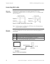
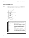
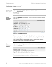
Light emitting diodes (LEDs)
LEDs
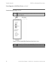
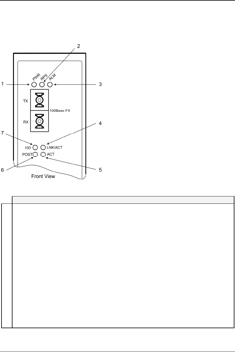
The Device Server has LED indicators located on its front panel. The LEDs present
at-a-glance network status, and provide real-time connectivity information. Figure 15
shows the LEDs and a chart that explains the function of each.
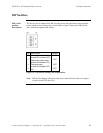
LED Description
1 Power (PWR) Lights green when input power is good
2 Redundant Power (RPS) Lights green when receiving external power from
redundant input source
3 Alarm (ALM) Lights red, signaling an alarm (when an external
alarm is connected) during a down link condition on
any port, or during primary/redundant power failures
4 LNK/ACT Lights green when connected to another device.
Flashes (amber) to indicate when the fiber port
receives link pulses from a compliant device (fiber
port only).
5 ACT Lights to indicate when the serial port is receiving
link pulses or data from a compliant device
6 POST Lights (amber) when the Power on Self Test was
successful; flashes when performing the POST
7 100 Lights (amber) to indicate when receiving data from
at 100Mbps (fiber port only)
Figure 15: LEDs and Description Chart