


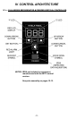
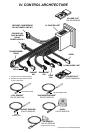
IV. CONTROL ARCHITECTURE
IV. b -
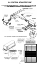
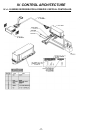
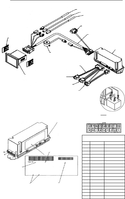
R & A SERIES REFRIGERATOR & FREEZER VERTICAL CONTROLLER:
Parts assembly for H1 thru MIT control versions only
-13-
6 Door Switch
5 Line Neutral
4 Door Heater
3 Blower
2 Line Voltage
1 Defrost
337-60317-00
2 12 VDC Coil
1 12 VDC Coil
DC 12-2001
HOLDER CLIP
337-60038-00
(set of two)
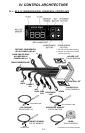
CONTROL HEAD
R/A 337-60318-00
G 337-60319-00
HF 337-60320-00
UC/UL 337-60321-00
HORN
337-60070-00
CABINET SENSOR - 337-60069-02
COIL SENSOR - 337-60071-02
DISCHARGE SENSOR - 337-60072-00
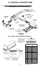
TO TRANSFORMER
(not included for MIT II versions)
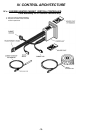
CONTROL CABLE
333-60250-00
RELAY BOX
337-60162-02
ADAPTER HARNESS
333-60249-00
TO DOOR RELAY
(door switch & line neutral)
TO DOOR HEATERS
(evap blower relay
power line in 1)
TO COMPRESSOR
& DEFROST RELAY
(power line in 2)
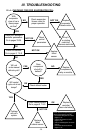
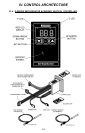
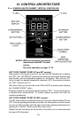
MIT CONTROL TROUBLE SHOOTING DIAGRAM
Date code will be listed
as the week-year (01-52)-
(2001-2100) when the
control is manufactured.
PIN connections may
not be available for
all model types.
Part numbers may
vary according to
model type.
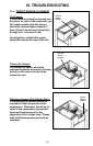
Remove the 4 screws (one
in each corner) & remove
the relay box cover to
expose pin connections &
transformer with voltage
setting jumper.
NOTE
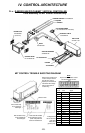
All pins in this connection should
not read more than 20 VAC
Connector
Pin No. Color Signal
1Gray Blower*
2 Orange Door Heater*
3 Green Alarm From Controller
4
5
6 Brown
7White/Purple -RS485
8Black Ground
9Yellow/Red 12 VAC
10 Blue Compressor*
11 Purple Defrost*
12 Yellow Door Open Signal
13 Red Power to Horn
14 Orange
15 White
16 Pink +RS485
17 Red 12 VDC to Controller
18
TO SSR COIL
CIRCUIT (MIT II ONLY)
337-60360-01 - see below
*Voltage should
not be more than
5 DC when
measured to
ground (pin 8).