


-8-
III. TROUBLESHOOTING
III. c - CHECKING FOR OTHER FAILED COMPONENTS:
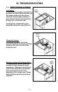
Checking For A Failed Door Switch:
1. Remove the door(s) from the unit involved.
2. Locate the door switch, which is located behind the top door hinge(s).
3. Remove the switch from the cabinet.
4. Using a volt/ohm meter (VOM), check across the switch contacts. “COM”
to “NO” should read open. If not, replace the switch.
5. Reinstall the switch and hinge onto the cabinet.
NOTE: If the unit has more than one door, check ALL door switches in the
same manner as described in steps 1 thru 5 above.
Checking For A Failed Controller Transformer
(H1 & MIT I control versions only)
:
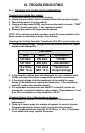
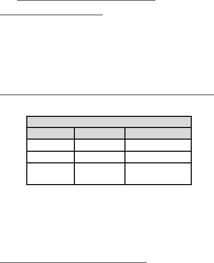
1. Check incoming voltage. Voltage at the unit must be within the ranges
shown in the table below.
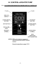
2. If the controller display does not come back on, use a volt/ohm meter
(VOM) and check the output voltage of the controller transformer.
3. If the output voltage from the transformer is not within the range
shown in the table above, replace the transformer. If the transformer
tests OK, replace the controller instead.
4. For equipment manufactured with the MIT II controller version the
transformer is mounted inside the relay module. Check between 17 and
8 on 18 pin connector on relay module for 12V DC.
Checking Cabinet, Coil or Discharge Line Sensors:
1. Gain access to CABINET, COIL or DISCHARGE LINE sensor and
disconnect it.
2. Place tip if sensor probe in a mixture of icewater for several minutes.
Allow enough time for sensor probe to aclimate to the icewater.
3. At 32°F, probe resistance shoud be 32.7K Ohms, +/- 10%. If resistance
is not within this range, repalce the sensor.
VOLTAGE
MIN MAX STANDARD
104 VAC 126 VAC 115/60/1
187 VAC 253 VAC 208-230/60/1
10.2 Volts 13.8 Volts Transformer
(MIT 12.4) (MIT 14.7) Output Voltage