


INSTALLATION Solid Pipe Installation
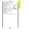
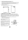
FITTING THE APPLIANCE AND CABINET.
1 Make suitable arrangements for gas and electrical supplies into the installation site. Preferably a junction
box or a 3 pin earthed socket should be situated at the back of the cabinet below the oven.
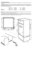
2 Fit cabinet as Fig. 1, making sure that it is level.
3 When unpacking the oven keep it on it's polystyrene base until it is put into the cabinet to avoid damage.
Do not allow young children to play with any part of the packaging. After installation, please dispose of
the packaging with due regard to the environment, your local authority can arrange this.
NOTE: It is imperative that the appliance is left in the base to protect both the appliance and the floor.
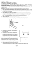
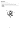
4 Open Oven door fully.
5 Rotate hinge stirrups to there forward position see Fig.2.
6 To remove the door, clear the hinges by raising the door slightly whilst pulling towards you.
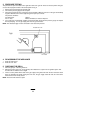
7 Solid gas pipe installation:
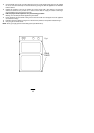
i) Remove the gas control knobs, springs, bezels and timer control knobs.
ii) Remove the four screws (two each side) which are visible on the underside of the fascia. Fig. 3.
iii) Tilt the bottom of the fascia panel out over. Withdraw the fascia panel by moving it down over to
disengage it from the top fixing lugs. Take care not to lose the two rubber grommets from the timer.
NOTE: The thermostat and grill discs will remain attached to the fascia panel. When refitting the control knobs and bezels, the
drive pins on the rear of the bezel must first be located in the disc carrier. The knob and spring can now be fitted onto the control
spindle. To prevent the top of the fascia panel mounts becoming slack, it may be necessary to adjust the top fixing lugs.
iv) Slacken and remove the union nut on the gas supply elbow on the right hand side of the control panel
see Fig.9.
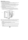
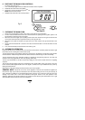
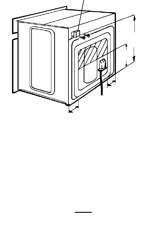
v) Remove the two screws on the gas inlet block Fig.5.
vi) Withdraw the gas inlet block and pipe assembly from the back of the appliance
vii) Remove the union elbow from the inlet block and pipe assembly. The elbow will be required in the
final installation.
viii) The union elbow should be connected to the gas supply pipe via a standard ¼"B.S.P. straight
connector.
8 Install the gas supply pipe on site complete with the union elbow (See Fig.6). Note the orientation of
the elbow.
9 Position the appliance in front of the cabinet and run the supply cable (See Section 2) through the
cabinet and connect to the junction box or socket. Ensure that the supply is isolated at this stage.
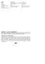
GAS INLET SUPPLY BLOCK
280
430
120
120
Fig.5
41