


6
Important Safeguards (Continued)
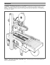
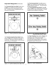
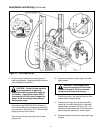
The "Box Centering Switch" label (A), shown in
Figure 1-13, is attached to the center plate on the
machine bed at the infeed end. The label identifies
the box centering switch.
The "Drive Assembly Raising Switch" label (B),
shown in Figure 1-13, is located above the switch at
the top/front of the upper drive assembly. The label
identifies the drive assembly raising switch.
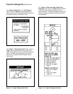
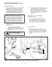
The "Centering Guide Force Adjust" label, shown
in Figure 1-11, is attached to the left side of the
machine frame over the centering guide control
knob. The label provides increase/decrease force
information to the operator.
Figure 1-11 – Centering Guide Force Adjust Label
Figure 1-13 – Box Centering Switch and Drive
Assembly Raising Switch Labels
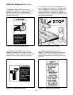
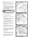
The "Tape Threading" label, shown in Figure 1-14,
is attached to the left side of both the upper and
lower taping heads. This label provides a
convenient tape threading diagram. More detailed
tape loading and threading information is provided in
the operation section of this manual.
The "Top Drive Assembly Force Adjust" label,
shown in Figure 1-12, is attached to the left side of
the machine frame over the top drive assembly
control knob. This label provides increase/decrease
force information to the operator.
Figure 1-12 – Top Drive Assembly Force Adjust Label
Figure 1-14 – Tape Threading Label