


10
Installation and Set-Up
Receiving And Handling
After the machine has been uncrated, examine the
case sealer for damage that might have occurred
during transit. If damage is evident, file a damage
claim immediately with the transportation company
and also notify your 3M Representative.
Machine Set-Up
Important – Read "Warnings", on page
19, before attempting to set-up the case
sealer for operation.
The following instructions are presented in the order
recommended for setting up and installing the case
sealer, as well as for learning the operating
functions and adjustments. Following them step
by step will result in your thorough understanding of
the machine and an installation in your production
line that best utilizes the many features built into the
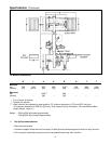
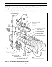
case sealer. Refer to Figure 3-1, page 15, to identify
the various components of the case sealer.
Note – A tool kit consisting of metric open
end and hex socket wrenches is provided
with the machine. These tools should be
adequate to set-up the machine, however,
other tools supplied by the customer will be
required for machine maintenance.
PACKAGING AND SEPARATE PARTS
1. Lift off fiberboard cover from pallet after
removing staples and straps at bottom.
2. Remove protective wrapping around machine.
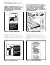
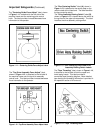
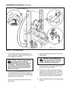
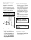
3. Install the upper tape drum bracket on the top
crossbar as shown in Figure 2-1A.
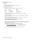
4. The column guards, shown in Figure 2-1 have
been installed upside down for shipping. They
must be repositioned for safe operation of the
machine. Remove and retain the screws and
washers holding the guards on the columns.
Rotate the guards 180° and install back on the
columns as shown. Replace existing screws
and washers to secure the guards in place.
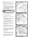
5. Cut cable ties securing upper assembly to
machine bed on each side.
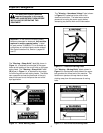
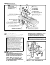
WARNING – Use care when working
with compressed air.
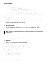
a. Read and remove safety tag from pneumatic
"On/Off" valve.
b. Connect the main air supply line to the inlet
side of the on/off valve using the barbed
fitting and hose clamp provided. See Figure
2-1B. The customer supplied air hose
(8 mm [5/16 inch] ID) must be clamped
tightly to the barbed fitting.
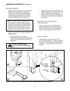
If another type of connector is desired, the
barbed fitting can be removed and replaced
with the desired 1/4-18 NPT threaded
connector.
Always turn the air valve "Off" when the air
supply line is being connected or
disconnected.
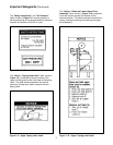
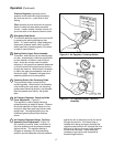
7. Turn the air supply on be turning the air on/off
valve to SUP (On).
Note – The air valve has provisions for lock
out/tag out according to plant regulations.
8. Raise and latch upper drive assembly in full "Up"
position.
6. Pneumatic connection.
CAUTION – Read "Operation –
Mechanical Latch", page 18, before
raising and latching upper drive assembly.
Note – A precision regulator is used to
balance the top drive assembly. Due to the
self relieving feature of this regulator a small
amount of air will continually vent to the
atmosphere. This is normal and amounts to
approximately 3 litre/min. [0.1 SCFM].
The case sealer requires a 5 bar gauge
pressure 110 litre/min [70 PSIG], @21°C, 1.01
bar [3.75 SCFM] compressed air supply. As
shown in Figure 3-1, an on/off valve, pressure
regulator, and filter are provided to service the
air supply.