13
Installation and Set-Up (Continued)
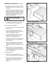
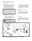
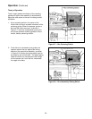
2. Loosen, but do not remove, two M8 x 1.25
socket head screws in one leg (use M6 hex
wrench). Adjust the leg length for the
desired machine bed height. Retighten the
two screws to secure the leg. Adjust all four
legs equally.
TAPE LEG LENGTH
Taping heads are pre-set to apply 70 mm
[2.75 inch] long tape legs. To change tape leg
length to 50 mm [2.0 inch], see "Special Set-Up
Procedure – Changing the Tape Leg Length",
page 29.
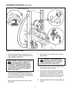
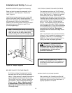
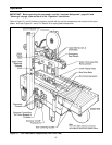
Figure 2-5 – Machine Bed Height Adjustment and Lower Tape Drum Bracket Position
Refer to Figure 2-5C and set the machine bed
height as follows:
1. Use appropriate material handling
equipment and blocking techniques to raise
the machine frame to allow adequate leg
adjustment.
CAUTION – Machine weighs
approximately 200 kg [430 pounds]
uncrated.
MACHINE BED HEIGHT
Adjust machine bed height. The case sealer is
equipped with four adjustable legs that are
located at the corners of the machine frame.
The legs can be adjusted to obtain different
machine bed heights from 610 mm [24 inch]
minimum to 890 mm [35 inch] maximum.
Note – Minimum machine bed height can be
reduced to 570 mm [22.5 inch] by moving
outer columns up one set of mounting holes.
However, this change also increases minimum
box height of 120 mm [4.8 inch] to 170 mm
[6.8 inch]. (See "Special Set-Up Procedure –
Box/Machine Bed Height Range", page 31.)
OUTBOARD TAPE ROLL MOUNTING
(Lower Taping Head)
Remove the tape drum bracket assembly,
spacer and fasteners from the lower taping
head. Install and secure on the infeed end of
the lower frame, as shown in Figure 2-5B.


