


32
Special Set-Up Procedure (Continued)
WARNING – Turn off electrical power and air supply and disconnect power cord from
electrical supply before beginning Special Set-Up Procedure. If power cord is not
disconnected, severe injury to personnel could result.
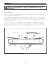
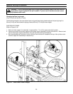
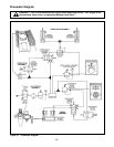
Box Height Range – (Refer to Figure 6-5)
The operating range of the upper drive assembly can be adjusted to minimize its movement to the range of box
heights being sealed. Therefore, the operating speed can be increased. The range is established by limiting the
lowest position of the drive assembly by positioning the stop bumpers at one of eight different levels on the side
columns.
The illustration in Figure 6-5 shows minimum box height with stop bumpers fastened through lower holes (A) at
different levels on the side columns. If bumpers are mounted with bolts through upper holes (B), the minimum
height of box in each position decreases by 20 mm [3/4 inch].
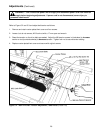
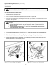
After establishing the minimum box height to be sealed, position the stop bumpers as follows:
1. Latch upper drive assembly in upper position, turn off air and electric.
2. Remove and relocate the stop bumper assembly to the desired position on both side columns. Be sure that
the stop bumpers are reassembled as shown and secure.
3. Turn on the air and electrical power to the case sealer. The upper taping head will now descend only part
way thus increasing operating speed.
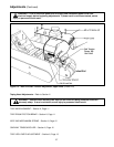
In addition to the bumper supports, adjustable split collars are fitted onto the cylinder rods as shown in Figure 6-5.
These can be used to stop the down position of the upper assembly at any position. To adjust these collars,
position the smallest box to be sealed under the drive belts and stop the machine. Slide the collars on both
cylinders down to the cylinder cap and tighten. Upper drive assembly will now stop at this position.
Figure 6-5 – Stop Bumpers