


20
Operation (Continued)
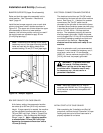
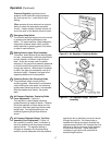
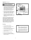
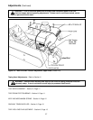
Figure 3-8 – Drive Assembly Raising Switch
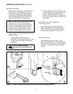
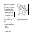
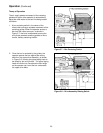
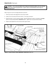
Figure 3-7 – Box Centering Switch
2. Once the box is centered by the guides, the
operator pushes the box against the raising
switch on the upper drive assembly, as shown
in Figure 3-8, causing the upper taping head to
be raised by two air cylinders. The upper taping
head will continue to rise above the box height
so the operator can insert the box underneath
the upper drive belts.
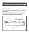
Theory of Operation
The air supply powers movement of the centering
guides and upper drive assembly to automatically
adjust the case sealer to the box size being sealed
as follows:
1. A box centering switch in the center of the
infeed roller conveyor actuates movement of the
centering guides. When the operator pushes a
box onto the infeed conveyor, as shown in
Figure 3-7, the lever is depressed causing the
air cylinder powered centering guides to move
inward, thereby centering the box.