


Disassembly Procedures
To avoid risk of electrical shock, personal injury or death;
disconnect power supply source before servicing, unless
testing requires it.
WARNING
!
RS2320006 Rev. 0 12
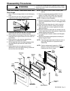
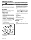
Reverse Procedure to Reassemble Oven
Door
Position slot on oven door hinge arms into the hinge
receivers. When slot is engaged into the hinge
receivers, open the door just far enough to rotate both
hinge locking tabs to the UNLOCK position.
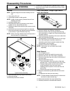
Oven Door Gasket
The braided fiberglass oven door gasket is clipped at
intervals in holes around the front of the oven liner then
inserted into a
3
/
8
inch holes at the bottom.
A 6
1
/
2
inch gasket void at the bottom does not interfere
with sealing of oven to door.
1. Unclip original gasket from front frame and pullout
ends from
3
/
8
inch holes.
2. Remove two knurled nuts securing oven bottom in
position. Remove oven bottom.
3. Divide oven gasket in half and insert center clip into
top center hole in the front frame. Proceed inserting
clips left and right.
4. Push gasket through the
3
/
8
inch holes. From behind
the holes gently pull on the gasket ends to provide a
neat appearance. Then tuck the ends between cross
brace and front frame. Assure that gasket ends are
not visible through air intake slots. If so, reposition
prior to installing oven bottom and oven door.
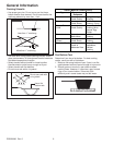
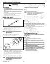
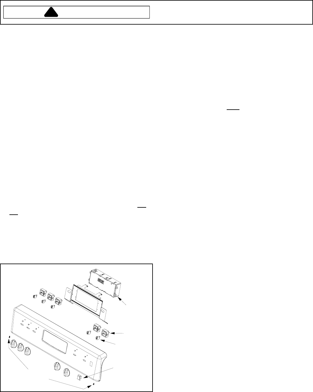
Electronic Control
1. Turn off electric supply to oven.
2. Using a stubby phillips screwdriver remove the
offset screws from the bottom front of control panel.
Offset
screws
Infinite
switch
Clock
Indicator
light
Rocker
switch
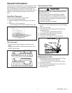
3. Rotate bottom of control panel outward, then lift up to
disengage top tabs.
4. Place control panel on a protective padded surface
with the control down. Remove screws securing
electronic control to mounting bracket. There is
sufficient extra wire length to move electronic control
out of the way while installing new control. Transfer
electrical wires/connectors one at a time to new
control.
NOTE: When reinstalling control panel, be certain the
fiberfax insulation and its galvanized retainer is
above the flue cutout in control panel. Insulation
and retainer are NOT visible when correctly
positioned. Verify backguard heat shield (above
flue) is inside backguard panel and not visible
when installed.
5. Reverse procedure to reattach control panel to range.
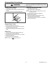
Infinite Switch
1. Turn off power to unit.
2. Remove backguard, see "Electronic Control"
procedure.
3. Disconnect and label wire terminals.
4. Remove infinite switch knob from infinite switch.
5. Remove screws in front securing infinite switch.
6. Reverse procedure to reinstall.
Indicator Light
1. Turn off power to unit.
2. Remove backguard, see "Electronic Control"
procedure.
3. Disconnect and label wire terminals.
4. Slide indicator light sideways to release from indicator
light lens.
5. Reverse procedure to reinstall.