


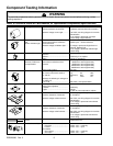
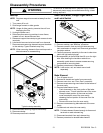
Component Testing Information
!
WARNING
To avoid risk of electrical shock, personal injury or death; disconnect power to oven before servicing, unless
testing requires it.
RS2320006 Rev. 0 8
Refer to Technical Sheet or Parts Manual for replacement components specifications.
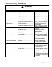
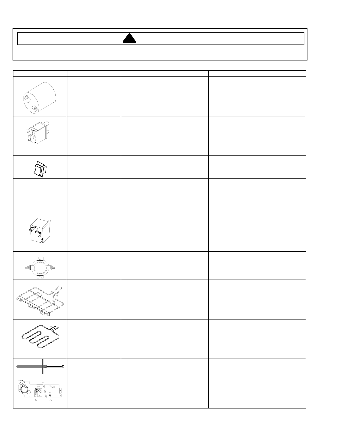
Illustration Component Test Procedure Results
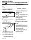
Oven light socket Remove one wire from receptacle
and test resistance of terminals.
Measure voltage at oven light...........
Indicates continuity with bulb screwed in.
120 VAC, see wiring diagram for terminal
identification.
If no voltage is present at oven light,
check wiring or light switches.
Oven indicator light
and
Surface indicator light
Remove one lead from switch
terminal and measure resistance
across terminals.
Measure voltage at indicator light.....
Switch closed: 0
Ω
Switch open: Infinite resistance
If voltage is present and light does not
operate. Replace light.
If no voltage is present at indicator light
check wiring.
Rocker switch Measure continuity of switch
positions:
Closed.............................................
Open...............................................
Continuity, if not replace.
Infinite, if not replace.
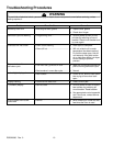
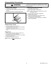
Ribbon radiant
elements, limiters are
not replaceable.
Remove one wire lead from element
and measure resistance of the
element.
Verify supply voltage ........................
Continuity, if not replace.
1200W:44 to 49
Ω
Approximately
1500W:36 to 40
Ω
Approximately
2000W:26 to 30
Ω
Approximately
2500W:20 to 23
Ω
Approximately
240 VAC
Infinite switch Remove wiring from terminals H1 and
H2. Connect Volt ohms meter to
H1 and H2.
Measure the following for voltages at
LO, MED, HI:
H1 to H2.........................................
Time On Time Off
LO 5% 95%
MED (4-5) 50% 50%
HI 100% 0%
240 VAC, if not replace switch.
Control limit Normally Closed
Verify proper operation.
Closed............................................
Open..............................................
Continuity
Infinite
If open at room temperature, replace.
Bake element Disconnect wire leads to element and
measure resistance of terminals.
Measure voltage at bake element.....
Continuity, approximately 20
Ω
,
if not replace.
240 VAC, see wiring diagram for terminal
identification.
If no voltage is present at bake element
check wiring.
Broil element Disconnect wire leads to element and
measure resistance of terminals.
Measure voltage at broil element......
Continuity, approximately 19
Ω
,
if not replace.
240 VAC, see wiring diagram for terminal
identification.
If no voltage is present at broil element
check wiring.
Oven temperature
sensor
Measure resistance.......................... Approximately 1100
Ω
at room
temperature 75
°
F.
Auto latch assembly Motor switch
Unlocked.....................................
Locked ........................................
Door switch
Door closed.................................
Door open...................................
COM
−
N.O.
continuity
COM
−
N.O.
open
COM
−
N.C.
continuity
COM
−
N.C.
open