


VARIETY STEAMER
18
P/N 1010745 Rev. G 03/06
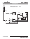
Technical Theory of Operation
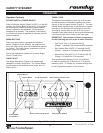
When the Rocker Switch (power On/Off) is ON, line
voltage flows to the primary side of the step down
transformer. The transformer’s secondary side supplies
12 and 24 VAC to the Control Board.
Once powered, and provided that the generator’s tem-
perature is below the setpoint temperature, the Control
Board calls for heat by supplying 3 to 5 VDC to the
Solid State Relay terminals 3 (+) 4 (-). Once powered,
the Solid State Relay then closes terminals 1 and 2,
which allows line voltage to flow to the generator.
As the generator begins to heat up, a type “K” thermo
-
couple monitors the internal generator temperature. As
the heat continues to increase, so does the thermocou-
ple’s DC millivolts.
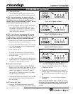
Once the generator’s temperature approaches the set-
point temperature, the Control Board begins to pulse
the VDC to the Solid State Relay. The generator’s VAC
and AMPS will also pulse during this point. When the
generator’s temperature is between the recommended
setpoints of 375 - 400° F (190 - 204° C), the thermo
-
couple generates approximately 7.5 - 8.5 DC millivolts.
The Control Board receives these millivolts and pro
-
ceeds to remove the 3-5 VDC to the Solid State Relay
since the heating circuit has now become satisfied.
Then, the Solid State Relay terminals 1 and 2 open up,
and the generator stops heating. The heating circuit
cycles on and off as needed, even at idle.
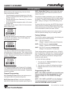
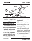
When the Single Shot button is pushed, it signals the
Control Board to initiate a single shot of steam. The
Control Board then supplies 24 VAC to the Solenoid
Valve for a split second. The Solenoid Valve opens and
allows approximately 3/4 - 1 ounce (4 to 5 tablespoons)
of water to be disbursed onto the generator surface
for steaming. The water is immediately converted into
steam, which is forced up through the black Manifold
Orifices to steam the product within the baskets.
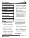
Each of the four channel buttons can be custom pro
-
grammed for cycle time, time between when each
steam shot occurs, and water volume used per each
shot (See the Programming section of this manual). An
audio signal will sound for three seconds at the end of
the cycle.
Two safety devices are incorporated into the VS-350:
• Hi-Limit Thermostat
• Pressure Relief Plunger
If the heating circuit continues to call for heat and the
generator overheats, a manual resettable Hi-Limit
Thermostat will trip and open the generator circuit.
If water and or steam pressure builds up beneath the
black Manifold Plate (due to restricted Manifold Plate
orifices), a Pressure Relief Plunger will elevate and vent
the steam pressure above the manifold plate.
NOTE: If any of these conditions should arise, the
root cause must be determined and corrected. See
the Maintenance section of this manual for further
details.
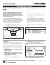
NOTE: All direct water fed units require a Water
Pressure Regulator. It should be set to 20-25 psi
(1.4-1.7 kg/cm
2
or 138-172 kPa). Failure to install a
Water Pressure Regulator will result in poor steam
-
ing and flooding of the steam generator.
MAINTENANCE (continued)