


5. Feed the wires of the replacement indicator lamp module through the opening and snap the new
indicator lamp module into place.
6. Reconnect wiring with each of the two new wires going to a different wire nut (it doesn't matter how
you match the new module wires). Re-tape over wire nuts and wires.
** Be sure to correctly match the other wires that were connected at the two wire nuts.
7. Replace the front panel (section 6-1b).
Required: Medium (6") flathead screwdriver, Medium (6”) phillips screwdriver, Wiring markers (color or
number codes), Electrical tape
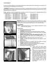
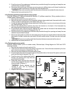
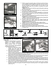
1. Remove front panel as found in section 6-1 b.
2. Mark all the wires connected to the thermostat indicator lamp module and thermostat with a color
code or number to make proper re-connection easy. (Fig. 11)
3. Locate the thermostat indicator lamp module wire that connects to a wire nut and remove that wire
nut, freeing all wires. (Fig. 13)
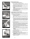
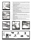
4. Remove the indicator lamp module wire from the terminal on the back of the thermostat by
removing the electrical tape and reversing the screw.
5. From the back side of the front panel, depress the plastic tabs on the base of the indicator lamp
module and push it out the front of the panel. (Fig. 12)
6. Feed the wires of the replacement indicator lamp module through the opening and snap the new
indicator lamp module into place.
7. Reconnect wiring with one of the two new wires going to the wire nut and the other to the back of the
thermostat (it doesn't matter how you match the new module wires). Re-tape over wire nuts and
wires.
Be sure to correctly match the other wires that were connected at the wire nut
8. Replace the front panel (section 6-1 b).
Required: Wiring markers (color or number codes), Electrical tape, Wiring diagram for CA43 and CA70
(see step 7 below)
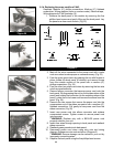
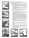
1. Remove front panel as found in section 6-1b.
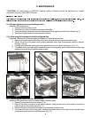
2. Trace the four wires from the power switch to the wire nuts. Code all wires connected by the four
wire nuts to insure proper re-connection. (Fig. 14)
3. Remove the wire nuts and free the power switch wires.
4. From the back side of the front panel, depress the plastic tabs on the base of the power switch and
push it out the front of the panel. (Fig. 15)
WARNING:
6-1d. Replacing the thermostat indicator lamp module.
*'WARNING:
6-1e. Replacing the power switch.
Figure 14
Figure 15
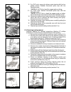
Diagram 1
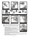
5. Feed the wires of the replacement switch
through the opening and snap the new
power switch into place.
6. Reconnect wires using the four wire nuts
and the wiring diagram. Re-tape over wire
nuts and wires. (Diagram 1)
Severe damage can be
caused to your unit by improperly
connecting wiring.
7. Replace the front panel (section 6-1b).
**WARNING: