


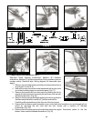


12. For CA70 units, secure fan blower motor bracket with the four
phillips screws. Reattach thermostat probe clips with two
flathead screws.
DO NOT kink or bend the copper probe or tubing.
13. For CA43 units, reattach thermostat probe clips with two
flathead screws.
DO NOT kink or bend the copper probe or tubing.
Secure fan blower motor bracket with the four flathead screws.
14. Reconnect existing wires to new motor wires. It is not important
which new wire is matched with which existing wire group.
Re-tape over wire nuts and wires.
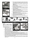
15. Replace fan blower motor housing cover, carefully guiding the
wires to prevent damage.
16. Replace fan blower motor assembly cover with two front and
two rear flathead screws.
17. Replace top mounted heating module (section 6-1 a).
**NOTE:
**NOTE:
6-1l. Replacing heating element.
Required: Medium (6") flathead screwdriver, Medium (6") phillips
screwdriver, Crescent wrench, General Electric 1209 caulking
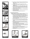
1. Remove top mounted heating module as found in section 6-1a.
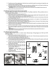
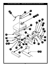
2. Remove four screws that secure the air deflector housing (on
your right as you are facing the front of heating module) to the
module with a medium (6”) flathead screwdriver.(Fig. 47)
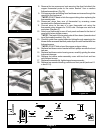
3. Gently lift the air deflector housing to access the nuts connecting
wires to the heating element. Remove those nuts and washers
to free the wires. (Fig. 48)
4. Remove air deflector housing" and place on a clean work area.
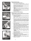
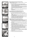
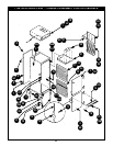
5. Remove four screws securing the heating element brackets to
the ceramic insulators with a medium (6") flathead screwdriver.
(Fig. 49)
6. Slide brackets off the old element and discard the old element.
7. Slide brackets (large one first) over the connector end of the new
heating element. (Fig. 50)
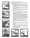
8. Reconnect heating element brackets to the ceramic insulators
with the four phillips screws. Do not over tighten.
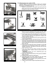
9. Return air deflector housing to the heating module and
reconnect wiring (it is not important which way you match the
wires to the new element). (Fig. 51)
10. Caulk openings where the heating element enters the air
deflector housing with GE 1209 caulking. (Fig. 52)
11. Reconnect air deflector housing to heating module with the four
flathead screws.
12. Replace top mounted heating module (section 6-1a).
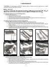
Figure 46
Figure 47
Figure 48
Figure 49
Figure 50
Figure 51
Figure 52