


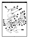


6-1m. Replacing the High-temperature safety thermostat.
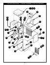
6-1 n. Replacing the top mounted heating module seal (gasket).
**NOTE:
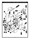
6.1o. Replacing the fan blower cooling fan for CA43 units.
Required: Medium (6”) flathead screwdriver, Medium (6") phillips
screwdriver, Crescent wrench
1. Remove top mounted heating module as found in section 6-1a.
2. Remove four screws that secure the air deflector housing (on your
right as you are facing the front of heating module) to the module with
a medium (6”) flathead screwdriver.
3. Gently lift the air deflector housing to access the nuts and connecting
wires to the high temperature safety thermostat. Remove those nuts
and washers to free the wires and the thermostat.
4. Attach the new high-temperature thermostat and reconnect the new
wires.
5. Reconnect air deflector housing to heating module with the four
flathead screws.
6. Replace top mounted heating module (section 6-1 a).
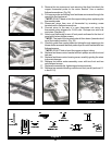
Required: Razor blade, General Electric 1209 caulking
1. Remove top mounted heating module as found in section 6-1a.
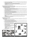
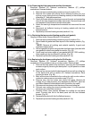
2. Razor blade old gasket and foam tape off of the heating module. (Fig.
53)
Remove all caulking and material carefully. A good seal
requires a clean surface.
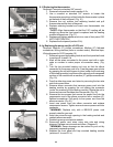
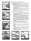
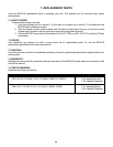
3. Set new gasket into place using double-face foam tape (included with
new gasket) to attach new gasket to module. (Fig. 54)
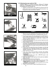
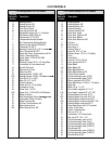
4. Caulk inner and outer edges of new gasket with GE 1209 caulking.
Allow caulking to dry for at least 45 minutes. (Fig. 55)
5. Replace top mounted heating module (section 6-1a).
Required: Medium (6”) flathead screwdriver, Medium (6”) phillips
screwdriver, Wiring markers (color or number codes), Electrical tape
1. Remove the back panel of the module by removing the five flathead
screws and gently removing the back panel. Lay the panel on a clean
work surface.
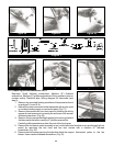
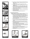
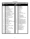
2. Remove four screws inside the back panel that secure the cooling fan
to the back panel with a medium (6”) flathead screwdriver. Save
spacers for reuse. (Fig. 56)
3. Mark all the wires connected to the cooling fan with a color code or
number to make proper re-connection easy. (Fig. 57)
4. Remove wire nuts and retain wire sleeve for reuse. Discard old
cooling fan (if under warranty and requested by BEVLES, send fan
and Return MaterialAuthorization form to the factory for credit).
5. Slip reserved wire sleeve onto the wires of the new cooling fan.
6. Connect new cooling fan wires to existing wires. It is not important
which way you match the new wires.
7. Carefully insert nylon spacers between the cooling fan and back
panel. Connect new fan to the back panel with the four flathead
screws. (Fig. 56)
8. Replace back panel with the five flathead screws.
9. Replace top mounted heating module (section 6-1a).
Figure 53
Figure 54
Figure 55
Figure 56
Figure 57