


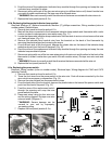
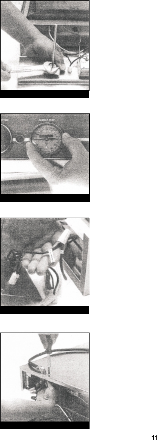
Figure 19
Figure 16
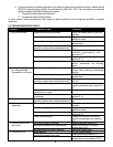
Figure 17
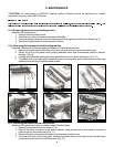
Figure 18
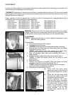
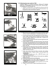
6.1f. Replacing the thermometer.
**NOTE:
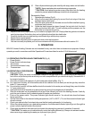
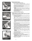
6-1g. Replacing the power cord for a CA70 unit.
Required: Crescent or standard 3/4" wrench
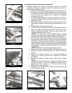
1. Remove front panel as found in section 6-1b.
2. Use a crescent or standard 3/4" wrench to loosen the
thermometer mounting nut that holds the thermometer in place
on the back of the front panel. (Fig. 16)
3. Remove the nut, washer and retaining bracket and pull
thermometer out the front of the panel.
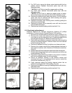
4. Replace retaining bracket and insert new thermometer into
opening.
Align thermometer so that the 150° reading will be
straight up when the front panel is replaced and the heating
module is flipped over. (Fig. 17)
5. Replace and tighten washer and nut on rear of front panel. DO
NOT OVER TIGHTEN!
6. Replace the front panel (section 6-1b).
Required: Medium (6”) phillips screwdriver, Medium (6") flathead
screwdriver, Wiring markers (color or number codes), Electrical tape,
Wiring diagram for CA70 (see step 10)
1. Remove top mounted heating module and front panel as found
in sections 6-1a and 6-1b.
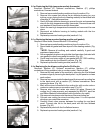
2. Mark all the wires connected to the power cord with a color
code or number to make proper re-connection easy. (Fig.
18) .
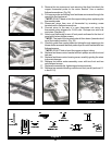
3. Turn the top mounted heating unit over so that the elbow
connector for the power cord is up. Free the green ground wire
by grasping the nut with fingers or pliers (under front overhang
of the heating module) and remove the screw from the exposed
surface of the module with a medium (6") phillips screwdriver.
(Fig. 19).
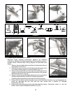
4. Free the other two power cord wires by removing the two wire
nuts that connect them.
5. Remove elbow connector that secures power cord into the
heating module by grasping the nut holding the connector
(under the overhang of the heating module). Rotate the nut to
loosen and remove the elbow from the module. (Fig. 20)
6. Remove the two screws that secure the power cord into the
compression end of the elbow connector with a medium (6”)
flathead screwdriver. Pull gently to free power cord from the
elbow connector. (Fig. 21)
7. Insert new power cord into elbow connector and replace
compression screws. Tighten screws to secure power cord into
connector.
: Replace only with a BEVLES power cord
properly rated for your unit.
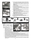
8. Insert new wires through opening in the heating module and
reattach elbow connector.
9. Reattach green ground wire to module.
10. Reconnect power cord wires using wire nuts and wiring
diagram. Re-tape over wire nuts and wires. (Diagram 2)
Severe damage can be caused to your unit by
improperly connecting wiring.
11. Replace the front panel and top mounted heating module
(sections 6-1a. and 6-1 b).
**WARNING
**WARNING: