


VR8105, VR8205, AND VR8305 DIRECT IGNITION COMBINATION GAS CONTROLS
69-1226—2 2
SPECIFICATIONS
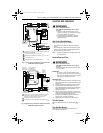
Body Pattern: Straight through; see Table 1 for inlet and
outlet size.
Electrical Ratings:
Voltage and Frequency: 24 Vac, 60 Hz.
Current Draw: 0.5A with both operators energized.
Capacity: See Table 1.
Conversion:
Use conversion factors in Table 2 to convert capacities
for other gases.
Regulation Range: See Table 1.
Natural-LP Gas Conversion Kits: See Table 4.
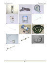
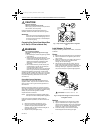
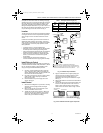
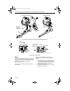
Pipe Adapters:
Angle and straight adapters available for 3/8-, 1/2- and
3/4-in. pipe. See Table 5. Flange kits include one
flange with attached O-ring, four mounting screws, a
9/64 in. hex wrench and instructions.
Approvals:
American Gas Association Design Certificate: L2025006.
Canadian Gas Association Design Certificate: L2025006.
Australian Gas Association Design Certificate: 4214.
Approved for Delta C applications.
European Community (CE) Certificate: Pending.
PLANNING THE INSTALLATION
WARNING
Fire or Explosion Hazard.
Can cause property damage, severe injury,
or death.
Follow these warnings exactly:
1. Plan the installation as outlined below.
2. Plan for frequent maintenance as described in
the Maintenance section.
Heavy demands are made on the controls when direct
ignition systems are used on central heating equipment
in barns, greenhouses, and commercial properties and
on heating appliances such as commercial cookers,
agricultural equipment, industrial heating equipment and
pool heaters.
Special steps may be required to prevent nuisance
shutdowns and control failure due to frequent cycling,
severe environmental conditions related to moisture,
corrosive chemicals, dust or excessive heat. These
applications require Honeywell Home and Building
Control Engineering review; contact your Honeywell
Sales Representative for assistance.
Review the following conditions that can apply to your
specific installation and follow the precautions
suggested.
Frequent Cycling
This control is designed for use on appliances that
typically cycle three to four times an hour only during the
heating season. In year-around applications with greater
cycling rates, the control can wear out more quickly.
Perform a monthly checkout.
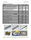
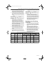
Table 4. Natural-LP Gas Conversion Kits
Table 5. Flange Adapter Part Numbers.
a
Flange kits include one flange, one O-ring and four mounting screws.
b
Do not use flanges on control models with 3/4 in. inlet and 3/4 in. outlet. On models with 1/2 in. inlet and 3/4 in. outlet,
use flanges only on the 1/2 in. inlet side.
Model No. Suffix Letter Kit to Convert Natural Gas to LP Kit to Convert LP to Natural Gas
H, K, M 393691 394588
P Not field convertible. Not field convertible.
Q 396021 396025
R Not required, convertible valve. Not required, convertible valve.
Inlet/Outlet
Pipe Size (in. NPT) Flange Type
Part No.
a,b
Without Hex Wrench With Hex Wrench
3/8 Straight 393690-1 393690-11
3/8 Elbow 393690-2 393690-12
1/2 Straight 393690-6 393690-16
1/2 Elbow 393690-3 393690-13
3/4 Straight 393690-4 393690-14
3/4 Elbow 393690-5 393690-15
69-1226-2.fm Page 2 Thursday, November 13, 2003 12:50 PM