


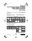
VR8105, VR8205, AND VR8305 DIRECT IGNITION COMBINATION GAS CONTROLS
7 69-1226—2
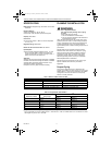
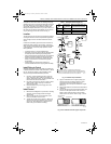
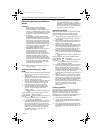
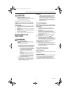
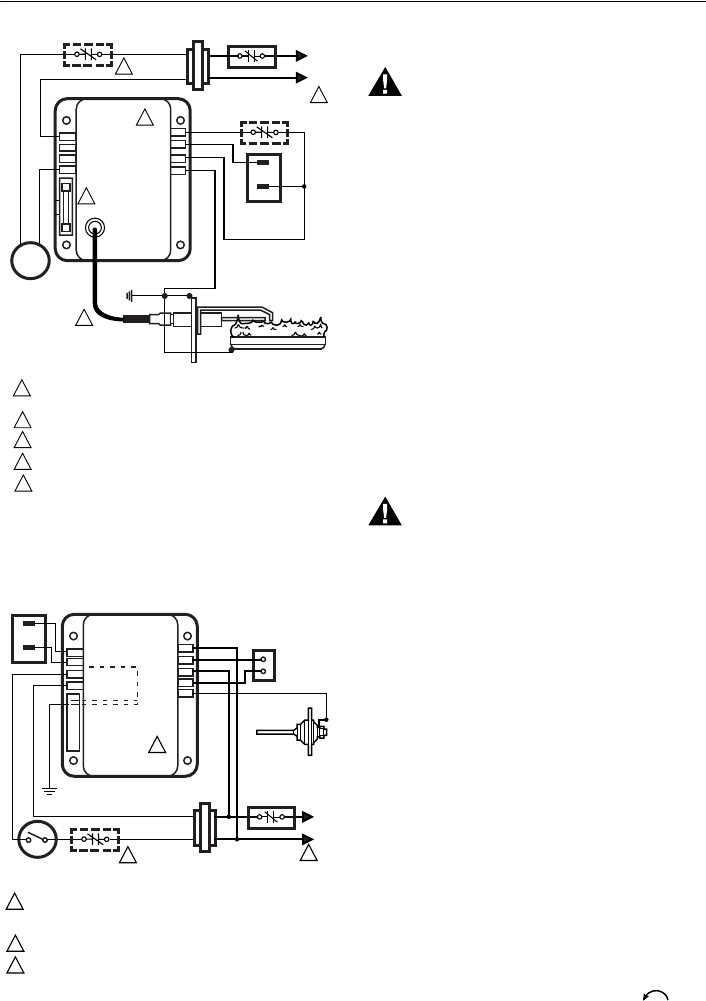
Fig. 7. Typical wiring connections for 24 volt control
in S87 Direct Ignition System.
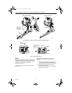
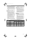
Fig. 8. Typical wiring connections with 24 volt control
in S89 Direct Ignition System.
STARTUP AND CHECKOUT
WARNING
Fire or Explosion Hazard.
Can cause property damage, severe injury
or death.
1. Do not force the gas control knob on the
appliance. Use only your hand to turn the gas
control knob. Never use any tools.
2. If the knob does not operate by hand, the
control should be replaced by a qualified
service technician.
Gas Control Knob Settings
Gas control knob settings are as follows:
• OFF: Prevents pilot and main gas flow through the
control.
• ON: Permits gas to flow into the control body. Under
control of the thermostat and direct ignition module,
gas can flow to the main burners.
NOTE: Controls are shipped with the gas control knob
in the ON position.
Perform Gas Leak Test
WARNING
Fire or Explosion Hazard.
Can cause property damage, severe injury
or death.
Perform Gas Leak Test every time work is done
on a gas system.
IMPORTANT
Do not spray soap and water solution on the
gas control. Do not use an excessive amount of
soap and water solution to perform the gas leak
test. These can damage the control.
Gas Leak Test
1. Paint pipe connections upstream of the gas control
with rich soap and water solution. Bubbles indicate
a gas leak.
2. If a leak is detected, tighten the pipe connections.
3. Light the main burner. Stand clear of the main
burner while lighting to prevent injury caused from
hidden leaks that could cause flashback in the
appliance vestibule.
4. With the main burner in operation, paint the pipe
joints (including adapters) and the control inlet and
outlet with rich soap and water solution.
5. If another leak is detected, tighten the adapter
screws, joints, and pipe connections.
6. Replace the part if a leak cannot be stopped.
Turn On System
Rotate the gas control knob counterclockwise to
ON.
Turn On Main Burner
Follow appliance manufacturer instructions or turn
thermostat up to call for heat.
24V
24V (GND)
S87 CONTROL MODULE
ALARM
VALVE
VALVE
GND
T
EMPERATURE
C
ONTROLLER
POWER SUPPLY. PROVIDE DISCONNECT MEANS AND OVERLOAD
PROTECTION AS REQUIRED.
ALTERNATE LIMIT CONTROLLER LOCATION.
MAXIMUM IGNITER-SENSOR CABLE LENGTH: 3 ft. [.9 m] OR LESS
.
3 A REPLACEABLE FUSE.
ALARM TERMINAL PROVIDED ON SOME MODELS.
M9043
MV
MV
L
1
(HOT
)
L
2
1
2
1
2
3
DUAL VALVE
COMBINATION
GAS CONTROL
Q347 IGNITER-SENSOR
BURNER
4
4
5
IGNITER-SENSOR AND
BURNER GROUND
3
5
ALARM, IF USED
WHITE
BLUE
BLACK
BLUE
HOT
SURFACE
IGNITER-
SENSOR
VALVE
VALVE (GND)
24V
TH-W
24V (GND)
GND (BURNER)
S89C,G,J/S890C,G,J
HOT SURFACE
IGNITION CONTROL
L2
HSI
L1
HSI
LIMIT
CONTROLLER
BURNER
GROUND
THERMOSTAT
OR CONTROLLER
DUAL VALVE
C
OMBINATION
G
AS CONTROL
POWER SUPPLY. PROVIDE DISCONNECT MEANS AND OVERLOAD
PROTECTION AS REQUIRED. MAKE SURE L1 AND L2 ARE NOT
REVERSED; THIS WOULD PREVENT FLAME DETECTION.
ALTERNATE LIMIT CONTROLLER LOCATION.
SEN TERMINAL AND Q354 FLAME SENSOR ON D MODELS ONLY.
M904
7
MV
MV
L
1
(HOT
)
L
2
VENT
DAMPER PLUG
1
2
1
2
3
3
SEN
Q354 FLAME
SENSOR
69-1226-2.fm Page 7 Thursday, November 13, 2003 12:50 PM