


VR8105, VR8205, AND VR8305 DIRECT IGNITION COMBINATION GAS CONTROLS
5 69-1226—2
Complete the instructions below for installing the piping,
installing the control, connecting the pilot gas tubing and
the wiring. Make sure the leak test you perform on the
control after completing the installation includes leak
testing the adapters and screws. If you use a wrench on
the valve after the flanges are installed, use the wrench
only on the flange, not on the control. See Fig. 5.
Location
The gas controls are mounted in the appliance vestibule
on the gas manifold. If this is a replacement application,
mount the gas control in the same location as the old
control.
Locate the combination gas control where it cannot be
affected by steam cleaning, high humidity, or dripping
water, corrosive chemicals, dust or grease accumulation
or excessive heat. To assure proper operation, follow
these guidelines:
• Locate gas control in a well-ventilated area.
• Mount gas control high enough above cabinet bottom
to avoid exposure to flooding or splashing water.
• Assure the ambient temperature does not exceed the
ambient temperature ratings for each component.
• Cover gas control if appliance is cleaned with water,
steam, or chemicals or to avoid dust and grease
accumulation.
• Avoid locating gas control where exposure to
corrosive chemical fumes or dripping water are likely.
Install Piping to Control
All piping must comply with local codes and ordinances
or with the National Fuel Gas Code (ANSI Z223.1, NFPA
No. 54), whichever applies. Tubing installation must
comply with approved standards and practices.
1. Use new, properly reamed pipe that is free from
chips. If tubing is used, make sure the ends are
square, deburred and clean. All tubing bends must
be smooth and without deformation.
2. Run pipe or tubing to the control. If tubing is used,
obtain a tube-to-pipe coupling to connect the
tubing to the control.
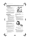
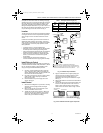
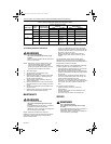
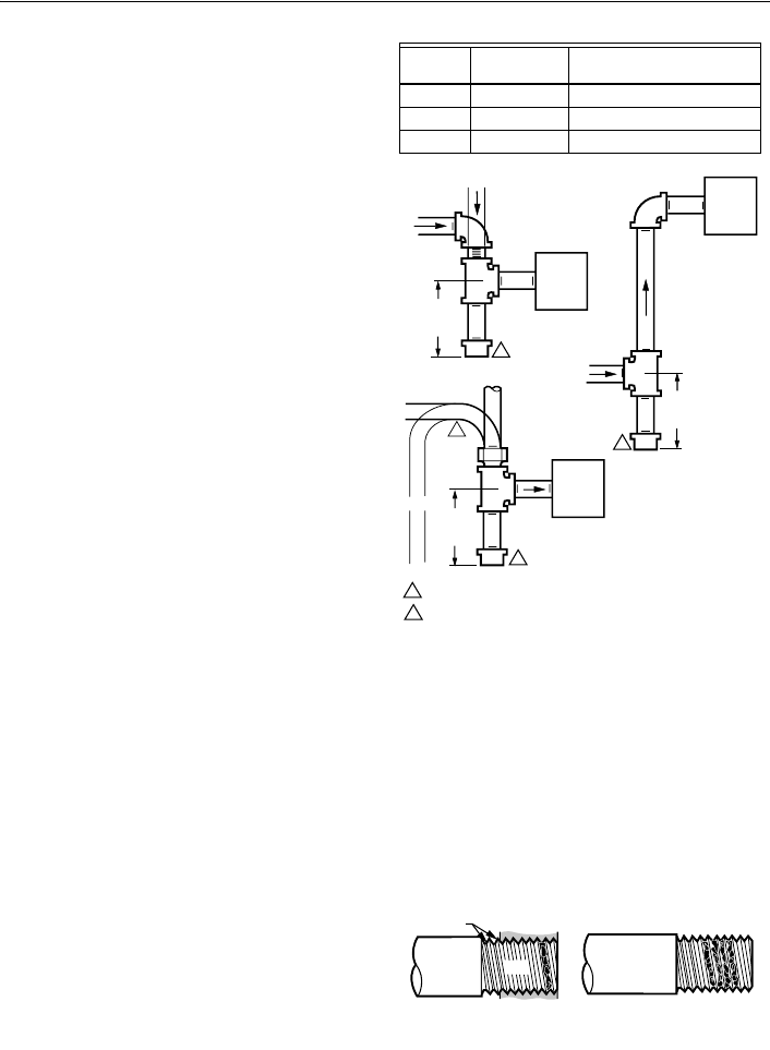
3. Install a sediment trap in the supply line to the
control. See Fig. 3.
Install Control
1. Mounted 0 to 90 degrees in any direction, including
vertically, from the upright position of the gas
control knob.
2. Mount so the gas flow is in the direction of the
arrow on the bottom of the control.
3. Thread the pipe the amount shown in Table 6 for
insertion into control or adapters. Do not thread
pipe too far. Valve distortion or malfunction can
result if the pipe is inserted too deeply.
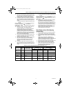
Table 7. NPT Pipe Thread Length (in.).
Fig. 3. Sediment trap installation.
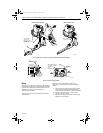
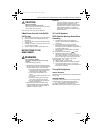
4. Apply a moderate amount of good quality pipe
compound (do not use Teflon tape) only to the
pipe, leaving two end threads bare. On LP
installations, use a compound resistant to LP gas.
See Fig. 4.
5. Remove the seals over the control inlet and outlet if
necessary.
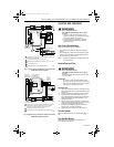
6. Connect the pipe to the control inlet and outlet. Use
a wrench on the square ends of the control. If a
flange is used, place the wrench on the flange
rather than on the control. Refer to Figs. 5 and 6.
Fig. 4. Use moderate amount of pipe compound.
Pipe
Size
Thread Pipe
this Amount
Maximum Depth Pipe can
be inserted into Control
3/8 9/16 3/8
1/2 3/4 1/2
3/4 13/16 3/4
GAS
CONTROL
GAS
CONTRO
L
HORIZONTAL
DROP
PIPED
GAS
SUPPLY
PIPED
GAS
SUPPLY
3 IN.
(76 MM)
MINIMUM
3 IN.
(76 MM)
MINIMUM
RISER
GAS
CONTROL
TUBING
GAS
SUPPLY
HORIZONTAL
DROP
3 IN.
(76 MM)
MINIMUM
RISER
M3077
2
1
2
2
1
2
ALL BENDS IN METALLIC TUBING SHOULD BE SMOOTH.
CAUTION: SHUT OFF THE MAIN GAS SUPPLY BEFORE REMOVING
END CAP TO PREVENT GAS FROM FILLING THE WORK AREA. TEST
FOR GAS LEAKAGE WHEN INSTALLATION IS COMPLETE.
TWO IMPERFECT
THREADS
GAS CONTROL
THREAD PIPE THE AMOUNT
SHOWN IN TABLE FOR
INSERTION INTO GAS CONTROL
APPLY A MODERATE AMOUNT OF
PIPE COMPOUND TO PIPE ONLY
(LEAVE TWO END THREADS BARE
).
M3075
B
PIPE
69-1226-2.fm Page 5 Thursday, November 13, 2003 12:50 PM